
User's Manual


FT-512 Trailblazer Installation and User Manual version 1.09 7
2 Installation
2.1 Unpacking
The FT-512 Trailblazer radio will arrive in one box approximately 19 x 15x 13
inches (47 x 37 x 32 cm). Small amounts of feed cable and/or power supplies
may also be included in this box if ordered.
Caution! Observe static precautions when wiring or handling circuit boards.
There are nylon standoffs holding the antenna element to the reflector plate.
These are fragile and can easily be over-tightened. They are set to a specific
torque and if over-tightened may fail.
2.2 Site Requirements
2.2.1 Lightning Protection
The FT-512 is equipped with secondary lightning protection only. If your feed
cable is more than 10 Meters (35 ft) in length or extends beyond the existing
building you will need a primary gas discharge type lightning protector. Contact
your sales representative for more information.
2.3 System Planning
2.3.1 Line of Sight, How to Tell for Sure?
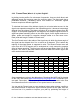
Microwave engineers will use a variety of ways to calculate the losses in a radio
path. Determining line of sight is easy if the path has a visible landmark at one
end. If that is not the case then one can resort to topographical maps and plot a
path. If this is marginal you still may have to prove the maps accuracy. We have
used a mirror as a reflector if a sunny day or if at night a bright spotlight. Even
with line of sight proven there are two more things you must know, distance and
clearance of first Fresnel zone.
!
!