
Datasheet


4 Specifications are subject to change without notice (05.09.2007)
RZ3A
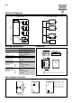
Connection Diagrams
Alarm Output Connection
VCC
Logic Input
B1
B2
RZ3A..
Alarm Output
VCC
Logic Input
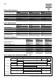
Housing Specifications
Weight Approx. 380 g
Material Noryl
Base plate
25, 55A Aluminum, nickel-plated
75A Copper, nickel-plated
Potting compound Polyurethane
Relay
Mounting screws M5
Mounting torque ≤ 1.5 Nm
Control terminal
Mounting screws M4
Mounting torque ≤ 0.5 Nm
Wire size Max. 2 x 2.5 mm
2
(AWG14)
Min. 2 x 1 mm
2
Power terminal
Mounting screws M5
Mounting torque ≤ 2.5 Nm
Wire size Max. 2 x 6 mm
2
(AWG8)
Min. 2 x 1 mm
2
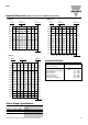
Heatsink
Compound
47.6
73.5
41
92
103
5.3
12
B1 B2
L1 L2 L3
T1 T2 T3
A1 A2
6xM5
4xM4
Relay On LED
Over-temperature Alarm Trip LED (suffix “P” option)
All dimensions in mm
B1
B2
Logic
Input
A1
A2
B1
B2
A1
A2
B1
B2
A1
A2
Regulation
ZC
ZC
ZC
Over Temp
Circuit
A1 (~) (+)
A2 (~) (-)
B1 (+)
B2 (-)
Control
Input
AC/DC
Alarm
Output
T1
T2
T3
L1
L2
L3
Output A
Output B
Output C
Terminal Wiring Common Alarm Wiring
Forward voltage ≤35 VDC
Reverse voltage ≤6 VDC
Through current ≤50mA
Alarm reset: interrupt control
input for more than 20ms
Active Low
Active High
Dimensions