
Datasheet


Specifications are subject to change without notice (28.02.2007) 3
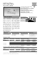
Increased Current Options
RP 1
I peak (Amps) 6 8 10
D5 : t (minutes) 15 5 3
D6 : t (minutes 15 5 3
t
T
amb
= 25°C
I
peak
I
nom
Note: Even though the D3 can withstand a slight increase
in current for a limited time, it is not recommended for
this purpose.
These relays can be used to switch heaters, motors, lights,
valves or solenoids.
When used at full load current, the relays must be placed
vertically. If more than one relay is mounted, please allow a
minimum distance of 20 mm in between for sufficient air
cooling.
Applications
1(~)
2(~)
3
4
REGULATION
ZC
IO
Functional Diagram
Control
input
Accessories
M1 DIN-rail adaptor (photo)
M2 DIN-rail adaptor (for V > 230VAC)
Varistors
Fuses
For further information refer to “General Accessories”.
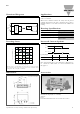
Derating Curve
Derating curve is used for finding max. load current at an elevated ambi-
ent temperature. The 3 lines in the graph represent the 3 nominal current
ratings of the RP1 series (RP1...D3/D5/D6).
4
6
5
3
2
1
0
D6
D5
D3
Housing Specifications
Weight Approx. 20 g
Housing material PBT, grey
Terminals Copper alloy, tin-plated
Terminals soldering temperature max. 300°C for 5 sec.
Potting compound Flame-retardant flexible
silicone rubber
(~)
(+)
3
(~)
(-)
4
2
1
20 30 40 50 60 70
Surrounding temp. (˚C)
Load current (AACrms)
Dimensions
* = ± 0.2 mm
** = ± 0.5 mm
43 *
10.5 **6 **
25.4 *
+1 2 +3 4
4 x ø1
11M
9M
4M
3M
1M
M = 1/10” = 2.54 mm