
Datasheet


Specifications are subject to change without notice (30.06.2011) 17
RGC...E
A
A11
AA 22
1
111++
11 22--
AA 11
AA 22
1111++
IINN33IINN22
11 22--
AA 11
AA 22
1111++
IINN33IINN22
11 22--
A1
A2
11+
IN3IN2
12-
A
1
A2
1
1+
IN3IN2
12-
A
1
A2
1
1+
IN3IN2
12-
A1
A2
11+
IN3IN2
12-
167.8
5
35.6
27.2
6
9.1
2
7.2
69.1
27.2
126
98
90
60.5
5
163
43.7
78
5
1
63
78
43.7
106
98
90
106
98
90
60.5
1
63
7
8
43.7
h
c
t
i
w
S
e
t
a
t
S
d
i
l
o
S
G
R
FAULT
CONTROL
A1
A2
FAN -
FAN +
GND
GND
SUPPLY
CONTROL
ALARM
OUT
IN
3
IN
2
IN
1
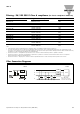
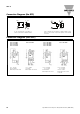
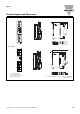
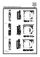
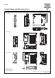
Terminal Layout and Dimensions (cont.)
* Housing width tolerance +0.5mm, -0mm…as per DIN43880
All dimensions in mm
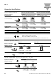
RGC...D90GGEP RGC...A90GGEP
1/L1: Supply connection
2/T1: Load connection
A1 (+): Positive control signal
(Positive supply in case of RGC1A..D90GGEP)
A2 (-): Control ground
IN1: Control signal (only for RGC1A.. D90GGEP)
IN2: Fan + supply (only for RGC1A60A90GGEP)
IN3: Fan - supply (only for RGC1A60A90GGEP)
11 + : Alarm output (+)
OUT, 12 - : Alarm output (-)
RGC...40GGEP
RGC...60GGEP
RGC...90GGEP