
Datasheet


Specifications are subject to change without notice (30.06.2011) 11
RGC...E
N
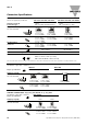
ote:
• Control input lines must be installed together to maintain products' susceptability to Radio Frequency interference.
• Use of AC solid state relays may, according to the application and the load current, cause conducted radio interferences. Use of mains filters may be
necessary for cases where the user must meet E.M.C requirements. The capacitor values given inside the filtering specification tables should be taken only
as indications, the filter attenuation will depend on the final application.
• Performance Criteria 1: No degradation of performance or loss of function is allowed when the product is operated as intended.
• Performance Criteria 2: During the test, degradation of performance or partial loss of function is allowed. However when the test is complete the
product should return operating as intended by itself.
• Performance Criteria 3: Temporary loss of function is allowed, provided the function can be restored by manual operation of the controls.
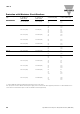
Filtering - EN / IEC 55011 Class A compliance (for class B compliance contact us)
Part Number Suggested filter for compliance Maximum Heater current
RGC1A23..15 68nF/ 275 V / X1 20A
RGC1A23..20 68nF/ 275 V / X1 20A
RGC1A23..30 220 nF / 275V / X1 30A
RGC1A23..40 220 nF / 275V / X1 30A
330 nF / 275V / X1 45A
RGC1A23..60 220 nF / 275V / X1 30A
330 nF / 275V / X1 45A
RGC1A23..90GGEP 330 nF / 275V / X1 35A
470 nF / 275V / X1 65A
RGC1A60..15 100 nF / 760V / X1 20A
RGC1A60..20 100 nF / 760V / X1 20A
RGC1A60..30 220 nF / 760V / X1 30A
RGC1A60..40 220 nF / 760V / X1 25A
330 nF / 760V / X1 45A
RGC1A60..60 220 nF / 760V / X1 25A
330 nF / 760V / X1 45A
RGC1A60..90GGEP 330 nF / 760V / X1 40A
470 nF / 760V / X1 65A
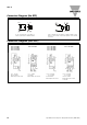
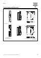
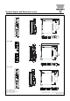
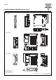
1 Phase
3 Phase
Filter Connection Diagrams
L1
L2
L3
R
d
= 1MΩ, 0.5W
N
Filter has to be connected
across both LOAD and SSR
SSR
R
d
SSR
SSR
LOAD
R
d
R
d