CARLO GAVAZZI Automation Components UDM 35/40 Digital Panel Meter Programming Guide
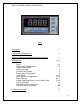
UDM 35/40 PANEL METER USER MANUAL Index Description 2 Programming Fundamentals 3 Access to Programming Mode/Password Protection 4 Programming Inputs Temperature Compensation Display Configuration Scaling the Inputs Decimal Point Position Display Span Configuration Linearization Alarm Set Point Configuration Digital Filtering Analog Output/Retransmission of Display Value Serial Port Output Fahrenheit/Celsius Conversion External Command Function UDMSoft User Guide 5-18 5-6 6-7 7 8 9 9 11-12 12-16 16-
UDM 35/40 PANEL METER USER MANUAL UDM Description The UDM 35/40 series is a universal Digital Panel Meter that has been developed to meet the most advanced application requirements.
UDM 35/40 PANEL METER USER MANUAL UDM 35/40 Programming Fundamentals There are no jumpers to consider when programming the UDM 35/40. The programming mode allows the user to define all of the instrument’s parameters.
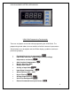
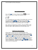
UDM 35/40 PANEL METER USER MANUAL Access to Programming Mode Press and hold for 2 seconds. Display will indicate (password). Within 2 seconds, four zeros “0000” will be displayed as follow: This is your prompt to enter your password. Each individual digit is selected from left to right by toggling the key. Changing the value of each digit is accomplished using the and arrows. When completed, press to confirm this step. If the password you entered is not correct, you will not be allowed access to program.
UDM 35/40 PANEL METER USER MANUAL Programming the Input Modules Press and hold for 2 seconds. Display will indicate PASS (password). Within 2 seconds, four zeros “0000” will be displayed. This is your prompt to enter your to confirm. You password. If zero “0000” is your password, simply press have approximately 20 seconds to begin programming before the unit reverts back to run mode. (To enter a unique password, see Access to Programming Mode, above.
UDM 35/40 PANEL METER USER MANUAL LSX and HSX input modules offer True RMS (trnS) or DC measurement (dC). Use keys to make selection. Press . Press keys to select Input signal integration time value (intt). If all zeros “0000” is selected, “Auto” will be displayed and the value will be automatically calculated from 100ms – 999.9 ms. Press to confirm. to advance to next program step sequence.
UDM 35/40 PANEL METER USER MANUAL Press key to select Auto (Auto). Press advance to next program step sequence. to confirm. . Press to Manual compensation should only be used in special applications. Consult factory. Configuring the Display (diSP) UDM35 only UDM 35 (BD35) base unit displays may be configured as 3 ½ digit (1999) or 3 digit + dummy zero (9990). When “diSP” is displayed, press . Then press keys to make selection. Press to confirm. Press to advance to next program step sequence.
UDM 35/40 PANEL METER USER MANUAL Scaling the Inputs When is displayed, access is available for configuring the electrical input range, the decimal point position and display span as follows: Electrical Input Range (HiE and LoE) Allows the operator to define an electrical input range different from the standard range setup at the “inP” programming step. As example, a UDM with a full-scale 20mA (19.99mA) setting, it is possible to select an electrical input range from 4.00mA (Lo.E) to 19.99mA (Hi.
UDM 35/40 PANEL METER USER MANUAL Decimal Point Position (dP) The decimal point position is relative to the Display Value, which will be discussed next. Using the and keys, select the When “dP” is displayed, press . decimal point position and press to confirm and advance to next step, “Lod” and “Hid”, the display span parameters.
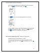
UDM 35/40 PANEL METER USER MANUAL Linearization Introduction is displayed, a signal from a non-linear transducer-sensor When may be modified by setting the input (in. 01 – in. 16) and output (ou. 01 – ou.16) linearization points so that the accuracy of the displayed value is maximized. This programming step is available when using the UDM40 and LSX/HSX input modules only. On the illustration below, the nominal output characteristics of an analog inductive proximity sensor is 4-20mA.
UDM 35/40 PANEL METER USER MANUAL Navigating & Programming within the Linearization Menu As appears, press followed by and keys to choose to ignore or enable linearization . Press to confirm your choice and advance to next step. If you chose YES, you will be prompted to enter the number of Linearization Points, using the escape button to select the position, and the up /down buttons to select to confirm and advance. the numerical value, from 01-16.
UDM 35/40 PANEL METER USER MANUAL Hysteresis selection Off-Delay Value (0-255s) On-Delay Value (0-255s) Relay Selection (normally energized or de-energized) Alarm Type (off, down, up, up with latch, down with latch) Color of display during alarm (red, orange, green, none) If “none” is selected, basic display color remains.
UDM 35/40 PANEL METER USER MANUAL Navigating through this program sequence Minimum Set-Point The lowest value, below which, it is not possible to program a set-point. When sequence. Press is first displayed, you have reached the Set-point program to enter program. The first parameter, Minimum Set-point Limit, will be displayed. To skip this step and advance to the next parameter, press the enter key . Otherwise, press the escape key to select the proper numerical position to enter a value.
UDM 35/40 PANEL METER USER MANUAL Hysteresis The point at which an active alarm output must revert to for the alarm output to turn off. Example: If an “up” alarm set point is “10.5”, and you want to have the alarm reset at “10.3”, then the Hysteresis value to set in the program must be “.2”, not 10.3. You need not be concerned about whether that value is to be in a positive or negative direction. That is automatically configured when you select the Down Alarm or Up Alarm.
UDM 35/40 PANEL METER USER MANUAL Configuring the Display Color for Alarm Event (UDM40/BD40 only) When is displayed, the color of the display may be set to be RED, ORANGE, or GREEN during the alarm event. Selecting NONE results in the basic display color being used during alarm event. Use the keys to make to confirm. Press to advance to the next your selection and press program step sequence.
UDM 35/40 PANEL METER USER MANUAL The second filter parameter is . It represents the filtering coefficient. The higher the value of Fil.C, the smoother the curve of the displayed value. There is no theoretical rule to define this parameter, but it is suggested to start with the same value of the Fil.S coefficient and then increase it until the desired stability is reached. The digital filter affects the values retransmitted via both serial communications and analog output.
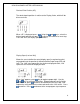
UDM 35/40 PANEL METER USER MANUAL Programming example: Retransmit a 4-20mA signal proportional to the following displayed values: Lo.D = 0 and Hi.D = 18. When is displayed, the Analog Output program may be addressed. Press to enter sequence. is displayed. Press to toggle to the first keys to select value “0”. Press to toggle to the left to position. Use the “tens” position. Using keys, select value “2” and press enter to confirm all choices and advance to the next program sequence. will be displayed.
CONVERTING CELSIUS TO FAHRENHEIT The UDM35/40 digital panel meters use the Celsius temperature scale. However, the displayed value can easily be scaled to indicate Fahrenheit values by using the following guidelines: The LoE and HiE are always expressed as Celsius values. To display Fahrenheit values, manually convert the LoD to a Fahrenheit value and then convert the HiD to a Fahrenheit value.
UDM 35/40 PANEL METER USER MANUAL External Command Function When is displayed, the user may elect to dedicate a Command signal (contact closure) from the input module, terminals 6 & 7, to perform one of the following: C1 C2 C3 Press the HOLD Function Disable-Keypad Reset latch Alarms to select Command sequence. Choose either C1, C2 or C3 by using keys to make your selection. Press to confirm.
UDMsoft Programming The software is menu driven. Just fill-in-the-blanks with your parameters. There is little explanation required. It is actually a simple process. Any confusion and concern that has surfaced has surrounded the issue of setup with the PC/laptop. The following segment is meant to clarify how to establish solid communication between UDM and PC. Do not connect or disconnect either end of the UCABLE when the input signal is connected to the input module.
UDM 35/40 PANEL METER USER MANUAL Links: Resources & Data Sheets UDM 35 Datasheet https://www.gavazzionline.com/images/UDM35DS5ENG0404.pdf UDM 40 Datasheet https://www.gavazzionline.com/images/UDM40DS5ENG0404.pdf UDM3540 Program Flow Chart UDM3540 Input-Output Modules UDM3540 FAQ (English) Panel Meter Selection Guide: https://www.gavazzionline.com/usameters.htm UDMSoft Downloads: https://www.gavazzionline.com/usadwnload.