
User Manual


Energy management
M-Bus Communication Protocol for EM24 M1
4
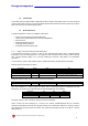
1.2.2 Request/Respond Procedure (REQ/RSP)
This procedure is requested from Master to Slave and typically generates the complete data transfer
from Slave to Master according to Class 2, EN 1434-3. All data are transferred through M-bus. The
complete serial Slave Response take four Long Frames. If the Slave has been previously programmed
through a Primary Data Request (SND_UD) then the Request/Respond Procedure (REQ/RSP) returns
only the selected data.
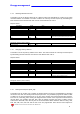
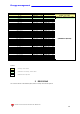
Long Frame EM24
#1 (transmitted first)
Energy Measurement -
System Power, System
Voltage and Current
Measurement
#2
Phase Power and Phase
Power Factors Measurement
#3
Phase Voltage
and Energy measurement
#4
DMD and Max DMD
Measurement
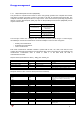
The DIF byte contains the coding for each transmitted parameter (32-bit integer or 16-bit integer).
VIF/VIFE bytes contain the measurement unit and its multiplier. There are three categories:
• Primary unit measurement
• Extended unit measurement
• User’s measurement
Each Data measurement available in EM24 is packed with its DIF, VIF, VIFE, Data field, this last
contains the numerical representation of the measured value. VIFE is not present in case of Primary unit
measurement. Transmission order is shown in Table 1. In the Data Field, the LSB is
transmitted/received first.
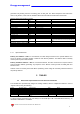
Request frame (From Master to Slave) – REQ_UD2 RSP_UD
Description Length Value Note
Start 1 byte 10h
Control 1 byte 01FV1011b
F = FCB-Bit
V = FCV-Bit (set to one if the FCB/FCV protocol is active)
Physical Address (Slave) 1 byte 1 to F7h (1 to 247)
Check Sum 1 byte
Check Sum; is the arithmetical sum (without carry) of the
Control Field and the Physical Address (Slave)
Stop 1 byte 16h
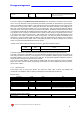
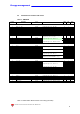
Response frame in case of correct action (From Slave to Master)
Description Length Value Note
Start 1 byte 68h
L Field 1 byte
L Field: is the bytes’ number calculated starting from the
Control Field up to the MDH Field (if the latter is present;
otherwise up to the last byte of the Data User).
L Field 1 byte See above.
Start 1 byte 68h
Control 1 byte 08h
Physical Address (Slave) 1 byte 1 to F7h (1 to 247)
CI 1 byte 72h
Ident. Nr. 4 Byte
Manufr. 2 Byte 1C36h “GAV”, ID Manuf. according to EN60870
Version 1 Byte Read from EM24
Medium 1 Byte 02h 02h = Electricity
Access No. 1 Byte Incremented after each REQ_UD2 procedure
Status 1 Byte
Signature 2 Byte 00h It is always 00 for all
DIF 1 byte Coding of the first transmitted value
DIFE 1 byte Coding of sub-unit only (max #4 DIFE)
VIF 1 byte Unit and Multiplier of the first transmitted value
VIFE 1 byte Unit and Multiplier of the first transmitted value (optional)
Data 2 or 4 byte First transmitted value (single measure)
…. … …
MDH 1 Byte 1Fh
In the last Long Frame of the slave the questioned byte is
0Fh. The latter (0Fh) indicates that the slave has been
completely read.