EM24 M1 M-BUS COMMUNICATION PROTOCOL Version 0 Revision 0 April 19th, 2013
Index 1.1 1.2 Introduction ...........................................................................................................................................3 M-BUS functions ...................................................................................................................................3 1.2.1 1.2.2 1.2.3 1.2.4 1.2.5 1.2.6 1.2.7 2 Single control character procedure SND_NKE ...................................................................
Energy management 1.1 Introduction The M-Bus interface implemented in EM24 M1 models, supports the M-Bus protocol. In this document only the information necessary to read Data Measurement from EM24 M1 has been reported (not all the parts of the protocol have been implemented). 1.
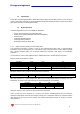
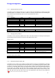
Energy management 1.2.2 Request/Respond Procedure (REQ/RSP) This procedure is requested from Master to Slave and typically generates the complete data transfer from Slave to Master according to Class 2, EN 1434-3. All data are transferred through M-bus. The complete serial Slave Response take four Long Frames. If the Slave has been previously programmed through a Primary Data Request (SND_UD) then the Request/Respond Procedure (REQ/RSP) returns only the selected data.
Energy management Check Sum 1 byte Stop 1 byte Check Sum: is the arithmetical sum (without carry) starting from Control Field to the MDH Field (if present, otherwise the last Data byte) 16h NOTE: each transferred measurement requires: DIF, DIFE (optional), VIF, VIFE (optional) and Data (2 or 4 Byte). See also Table 1 The device supports the FCB/FCV-bit transfer protocol.
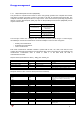
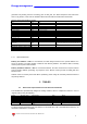
Energy management 1.2.4 Switching Baudrate Function The Master can set the Slave’s Baud rate to a different value from 300 BAUD as a matter of fact, 2400 and 9600 BAUDs are available. The Slave confirms the correctly received request by transmitting the E5h character and the old baudrate and uses the new baudrate from now on.
Energy management generated only starting from the next REQ_UD2 RSP_UD. The Slave Response could take more than a Long Frame, in this case the FCB/FCV-bit Protocol should be activated from the Master.
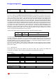
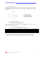
Energy management 2.1.1 Geometric representation According to the signs of the power factor , the active power P and the reactive power Q, it is possible to obtain a geometric representation of the power vector, as indicated in the drawing below, according to EN 60253-23: a = Exported active power b = Imported active power c = Imported reactive power d = Exported reactive power Fig. 1 : Geometric Representation 2.
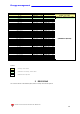
Energy management 2.3 Instantaneous variables and meters Table 1 - EM24DIN Length (byte) VARIABLE ENG.
Energy management Measurement Unit Watt*0.1 Wh*100 Volt*0.1 VAR*0.1 PF*0.001 Hz*0.1 VARh*100 VA*0.1 Hour*0.01 Wh(-)*100 (exported energy) VARh(-)*100 (exported energy) Watt L1*0.1 Watt L2*0.1 Watt L3*0.1 Wsys DMD*0.1 Wsys DMD max*0.1 Ampere L1*0.001 Ampere L2*0.001 Ampere L3*0.001 Ampere DMD max*0.001 Volt L1-N*0.1 Volt L2-N*0.1 Volt L3-N*0.1 Volt L1-L2*0.1 Volt L2-L3*0.1 Volt L3-L1*0.1 VA L1*0.1 VA L2*0.1 VA L3*0.1 VAsys DMD*0.1 VAsys DMD max*0.1 VAR L1*0.1 VAR L2*0.1 VAR L3*0.1 PF L1*0.001 PF L2*0.