
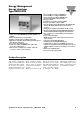
Datasheet
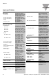


Specifications are subject to change without notice EM24 DIN DS 260315 5
EM24 DIN
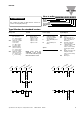
Connections 2-wire
Max. distance 1000m
Addresses 247, selectable by means of
the front joystick
Protocol MODBUS/JBUS (RTU)
Data (bidirectional)
Dynamic (reading only) System and phase
variables: see table “List of
variables...”
Static (reading and writing) All the configuration param-
eters.
Data format 1 start bit, 8 data bit, no
parity,1 stop bit
Baud-rate 4800, 9600 bit/s
Driver input impedance 1/5 unit load
Maximum 160 transceivers
on the same bus.
Insulation By means of optocouplers,
4000 VRMS output to
measuring input,
4000 VRMS output to
power supply input.
M-bus
Type One-drop, directional
Connections 2-wire, max. distance
according to EN13757-1
Addresses
Indirizzo primario 247, selectable by means of
the front joystick and via M-
bus (default 0). The primary
address can be set to 0
again after begin set to
another value only via M-
bus.
Secondary address Predefined, univocally pre-
sent during manufacturing
Protocol M-bus according to
EN13757-1
Available data and frame format See table “M-bus available
variables and frame format”
Baud-rate 300, 2400 (default), 9600
bits/s
Baud-rate selection Set during programming or
set directly by the M-bus
master
Driver input capability 1 unit load
Special functions None
Insulation By means of optocouplers,
4000 VRMS output to
measuring input
Note (for RS485 and
M-bus ports) The meters equipped with
the communication port
(“AV9” models with “M1”
and “IS” options) work even
if VL3 is missing (VL1, VL2
and neutral have to be
available)(see table “work-
ing mode notes”)
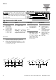
Digital outputs
Pulse type
Number of outputs Up to 2, independent.
Programmable from 0.001
to 10.00kWh/kvarh by
pulse.
Type Outputs connectable to the
energy meters (kWh/kvarh)
Pulse duration T
OFF
≥120ms, according to
EN62053-31
T
ON
selectable (30 ms or
100 ms), according to
EN62053-31
Alarm type
Number of outputs Up to 2, independent
Alarm modes Up alarm, down alarm (see
the table “List of the
variables that can be
connected to”)
Set-point adjustment From 0 to 100% of the
display scale
Hysteresis From 0 to full scale
On-time delay 0 to 255s
Output status Selectable; normally
de-energized or normally
energized
Min. response time ≤ 700ms, filter excluded,
set-point on-time delay: “0 s”
Note The 2 digital outputs can
also work as a dual pulse
output, dual alarm output,
one pulse output and one
alarm output.
Static output
Purpose For pulse output or alarm
output
Signal V
ON
1.2 VDC/ max. 100 mA
V
OFF
30 VDC max.
Insulation By means of optocuplers,
4000 VRMS output to
measuring inputs,
4000 VRMS output to
power supply input.
Relay output
Purpose For alarm output or pulse
output
Type Relay, SPST type
AC 1-5A @ 250VAC
DC 12-5A @ 24VDC
AC 15-1.5A @ 250VAC
DC 13-1.5A @ 24VDC
Insulation 4000 VRMS output to
measuring input
4000 VRMS output to
power supply input.
Note The meters equipped with
the relay outputs (“AV9”
models with “R2” option)
work even if VL3 is missing
(VL1, VL2 and neutral have
to be available)(see table
“working mode notes”)
RS485
Type Multidrop, bidirectional
(static and dynamic
variables)
Output specifications