
User Manual

Energy management
EM24-DIN PFA, PFB & X models - Communication Protocol
7
2 TABLES
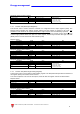
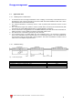
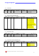
2.1 Data format representation In Carlo Gavazzi instruments
The variables are represented by integers or floating numbers, with 2’s complement notation in case of
“signed” format, using the following:
Format IEC data type Description Bits Range
INT16 INT Integer 16 -32768 .. 32767
UINT16 UINT Unsigned integer 16 0 .. 65535
INT32 DINT Double integer 32 -2
31
.. 2
31
UINT32 UDINT Unsigned double int 32 0 .. 2
32
-1
UINT64 ULINT Unsigned long integer 64 0 .. 2
64
-1
IEEE754 SP Single-precision floating-point
32 -(1+[1 –2
-23
])x2
127
.. 2
128
For all the formats the byte order (inside the single word) is MSB->LSB. In INT32, UINT32 and UINT64
formats, the word order is LSW-> MSW.
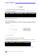
2.1.1 Geometric representation
According to the signs of the power factor , the active power P and the reactive power Q, it is possible
to obtain a geometric representation of the power vector, as indicated in the drawing below, according
to EN 60253-23:
Fig. 2 : Geometric Representation
a = Exported active power
b = Imported active power
c = Imported reactive power
d = Exported reactive power
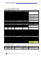
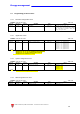
2.2 Maximum and minimum electrical values in EM24-DIN
The maximum electrical input values are reported in the following table. If the input is above the
maximum value the display shows “EEEE”.
Table 2.1-1
AV9 input option AV2 input option AV5 input option
Max value Min value Max value Min value Max value Min value
VL-N 280V
0
280V
0
280V
0
VL-L 485V
0
485V
0
485V
0
A 65A
0
65A
0
11A
0
VT ratio
6000
1.0
CT ratio
60000
1.0
The overflow indication “EEEE“ is displayed when the MSB value of the relevant variable is 7FFFh.