
User guide


Model 90200H/HT Microprocessor Temperature Controls — Instructions
Where appliance instructions differ from this manual, follow the appliance instructions.
- 2 - Carlin part number MN90200HM Rev. 04/16/09
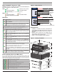
Model 90200H/HT diagnostic LED’s
90200H/HTcontrolshaveagreenLED(power&faultindicator)andamberLED(ringrate
percent&faultindicator).SeeLEDconditionsbelow.
GREEN
–OFF –ON(Indicates control is oprational)
–Short on/Long off flash –Long on/Short off flash
–FLASH uniformly (aboutoncepersecond,equalon/offdurations)
AMBER –OFF –ON
–Short on/Long off flash –Long on/Short off flash
–ON time equals firing rate percentage
Operation
LED’s Control status
Power Off: When no power is applied to the Red-White wire, the modulating
output is at LOW FIRE.
Power On: When power is applied to the Red-White wire, the circuit is energized
starting the Fault Log Display followed by the Self Test. When these are complete
the control becomes operational and turns the Green LED on steady
See Fault log display below — faults will display when power is applied.
NOTE: When flashing, the LED’s flash once every second in Fault display mode. The
green LED flashes once every 3 seconds when in Self Test mode.
Self Test: When the fault log display is complete, the self test checks the sen-
sor and the microprocessor and internal circuits. This test lasts up to 6 seconds
before the control becomes fully operational. During the self test the green LED
flashes on once every 3 seconds.
Burner @ High-Fire: When the sensor temp is at or below the operating
temp minus 1/2 the modulating band, the modulation signal is at High-fire. The
Amber LED is full on.
Burner @ Low-Fire: When the sensor temp is at or above the operating
temp plus 1/2 the modulating band, the modulation signal is at Low-fire. The
Amber LED is full off.
Burner in Proportional Modulation: When the sensor temperature is in
the modulating band (1/2 the band setting either side of the operating temp),
the control modulation signal varies proportionally between high and low fire. The
Amber LED flashes proportionally. The percentage of time the LED is on equals
the modulating output percentage.
Lockout: The control goes into lockout on ANY of the fault code conditions
and Logs the fault code indicated below under “Fault log display.”
While in lockout, the Motor modulation output is at low fire. The Amber LED is
off. The green LED flashes uniformly once per second.
Reset from Lockout:The control automatically resets from Lockout when
ALLconditionsreturntonormal.Thecontrolreturnstowhateverstateisdened
byitsinputs.
Latch-up:ControlgoesintoLatch-uponhardwarefailure.Controlshouldbere-
placed.ThegreenLEDisoff.TheamberLEDison.(Thiswilloccurimmediatelyif
poweristurnedoffandbackonagainincontrolisinlatch-up.)
Fault log display (based on LED status)
If the control has detected a fault condition, it will display the fault conditions when
power is turned off, then turned on again. Each fault code will occur 4 times. The control
will then display the next fault code, if any. The fault log is erased after displaying the
results. The codes will display in the following sequence:
1
Internalcontrolmicroprocessorfailure.
2
Temperaturesensorisshorted.
3
Temperaturesensorisopen.(Repeatsthesamecode)
4
Internalcontrolmicroprocessor—pinisopen.
5
Modulatingbandinternalcircuitisopen.
6
Operatingtemperatureinternalcircuitisopen.(Repeatsthesamecode)
7
Controlinternaldiagnosticfailure.
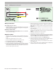
Figure 1 Wiring connections
White
N
H
Service
switch
Red/White
120
VAC
90200H
135-ohm
modulated
device
To sensor
Sensor
W
R
B
Yellow/White
Yellow/Red
Yellow/Black
White
N
H
Service
switch
Red/White
120 VAC
90200HT
135-ohm
modulated
device
To sensor
Sensor
W
R
B
W
R
B
Swap connections to B and W to reverse the motor direction.
Configurations
• Control kits —90200H/HTcontrolsmounttoastandard4x4J-box,
suppliedwiththecontrol.Mounttheboxdirectlytoawell(newor
existing)withhardwaresupplied,orpanelmount.SeeFigure2for
dimensions.
• Well kits —Wellsfor90200Hsensorsareavailableinthesizes
shownin Figure2.Wellkits include sensormounting hardware
designedtoholdsensorsecurelyinposition.
• Sensors —Sensorsareavailableinsinglecongurations.
Figure 2 Mounting the 90200H/HT