
User guide

Carlin part number MNEZ123 Rev. 07/13/11
– 7 –
Model EZ-1/2/3 oil burners — Instruction manual
2. Prepare site • assemble burner • mount burner (continued)
Verify combustion chamber
General guidelines
• If retrofitting the burner to an appliance, install the burner in accordance
with the appliance instruction manual, when available. If no specific
application data is available from the appliance manufacturer, apply
the guidelines in Table 3 to check whether the burner is likely to work
acceptably in the application.
• Cleanallapplianceuesandheatingsurfacesthoroughly,removing
all soot and scale.
Sealalljointsandgapsusingfurnacecementtopreventexcessairinltration.
Minimum combustion chamber dimensions
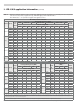
• IllustrationsAtoCinTable3showdifferentchambercongurations.
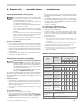
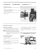
Table 3 Burner retrofit applications — guidelines and minimum dimensions for combustion chambers
Verify clearances
Verify that the burner/appliance will maintain all clearances from combustible
construction and clearances for service/maintenance as required in the appliance
manual and applicable codes.
Verify that the vent system components maintain all necessary clearances to
combustible construction, including the correct design of thimbles and insulation
where penetrating combustible walls.
• Donotattempttoretheburnerinachamberwithdimensionssmaller
than shown in Table 3 unless the application has been specifically tested
and listed by the appliance manufacturer and/or Carlin.
• Please notice the special requirements given in Table 3 notes.
Using chamber linings and lightweight chambers
• When using refractory liners or lightweight chambers, use insulating-
type refractory rated 2300°F minimum.
• Youmustinstallatargetwalllinerifamelengthisclosetothelength
of the chamber.
• Useaoorlinerwhenpossible.Theoorlinerwillimproveringinmost
applications.Extendoorliner3to4inchesupsidewall.
• Target wall liners — Corbel the top of target wall liners 1½ to 2½ inches
deepandextendatleast3to4inchesabovethecenteroftheame.
• Use pre-formed chamber liners when available.
• Forringratesbelow0.75GPH,itisbesttoapplyinarefractory-lined
orstainlesstube(designedforapplication)chamber.Liningtheoor
and target wall of the chamber with lightweight insulating refractory
will accomplish the same.
• When conversion firing coal-fired units, install a combustion chamber in
the ashpit area, or fill ashpit with sand up to 2 inches above the “mud
ring”ofaboiler(ringthroughthedoor).Installalightweightrefractory
liner on the target wall as in Table 3, Figure C. Make sure the minimum
dimensions comply with those listed.
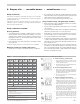
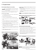
A. Conversion firing coal-fired units
1. Install a combustion chamber in the ashpit area, or fill
ashpitwithsandupto2inchesabovethe“mudring”
ofaboiler(ringthroughdoor).
2. When firing through door, install a lightweight refractory
“target”ontherearwall,asshown.
B. Conversion firing dry-base units
1. Appliesto brick, refractory, precastand preformed
refractory fiber chambers. Lightweight, insulating-type
materials are preferred because of their quick warm-up.
Use material rated at least 2300°F.
2. Dimensionsinthetablecanbeexceededwithoutmuch
effect for dry-base units.
C. Conversion firing wet-based units
1. Applyrecommendations here to prevent ame from
impinging on surfaces or being cooled too much by the
coolwallsoftheheatexchanger.Donotexceeddimen-
sionsoftablemorethan50%toavoidamechilling.
2. Installaceramicberoorliner(extended3to4inches
upthesidewalls)andaceramicberreartargetthe
full width of the back wall as well. Corbel the top of
thetarget1½”to2½”deepandextendatleast3to4
inchesabovethecenteroftheame.Usepreformed
chambers and/or target walls if available.
3. Setthefuelunitpressureforapproximately150PSIG
and use a nozzle rated about 20% less than the firing
rate to compensate for the higher pressure. This will
improveatomization,makingtheamemoreintense,
shorter and hotter. Use a head bar matched for the
nozzle size, but set the air band to match the firing
rate.
1
Firing rate
2
L
3
W
4
C
5
H
6
DV
GPH Inches Inches (3) Inches Inches Inches (5)
0.50
7 6 3 8 7
0.65
7.5 7 3.5 9 7.5
0.75
8 7 3.5 9 8
0.85
9 7 3.5 9 8.5
1.00
10 8 4 10 9
1.10
11 8 4 10 9.5
1.25
12 8 4 10 10
1.35
13 8 4 10 11
1.50
14 8 4.5 11 12
1.65
15 9 4.5 11 13
1.75
16 9 4.5 11 14
2.00
17 9 4.5 11 15
2.25
18 10 5 12 16
2.50
19 10 5 12 17
Notes
1 Some tested appliances operate well with dimensions other than above.
2 Generally, the application should be acceptable for dimensions as large as 50%
greater than the above.
3 Horizontal cylinder chambers should have a diameter at least as large as the
dimension in column 3.
Horizontal steel cylinder chambers should have diameters at least 1 to 4 inches
larger than the dimension in column 3.
4 Wing walls are not recommended. Corbels can be benecial to heat distribution
in some appliances.
5 DV is the minimum diameter for vertical cylinder chambers.