
User guide

Carlin part number MNEZ123 Rev. 07/13/11
– 6 –
Model EZ-1/2/3 oil burners — Instruction manual
2. Prepare site • assemble burner • mount burner (continued)
Combustion/ventilation air checklist
The burner may operate successfully under momentary
downdraft conditions, but sustained downdraft is un-
safe. This can occur with an inadequate or incorrectly
installed chimney/vent. It can also occur in rooms/
buildings equipped with exhaust fans or unsealed
return air ducts.
Alwayscheckoperationoftheburnerunderallcondi-
tions to verify vent system operates correctly.
Combustion/ventilation air openings:
Alwaysprovidecombustion/ventilationairtotheappli-
ance room sufficient to prevent any negative pressure
in the space — if necessary, install new or additional
airopenings.Seeinstructionsinthismanual.
Piped combustion air applications:
BurnerswithpipedcombustionairrequiretheField
CAS-1combustionairsystem.Thisincludesavacuum
relief valve that will cause combustion air to be taken
from the room if the combustion air piping becomes
blocked or if any condition causes a vacuum in the
air piping. The equipment room must have adequate
air openings to provide combustion air should this
occur.Seeinstructionsinthismanualforcombustion
air openings.
Failure to correct downdraft or negative room pressure
operation could result in severe personal injury, death
or substantial property damage.
❏ Verify that openings are unobstructed.
❏ Verifythatappliancespaceandairsourcespacesarefreeof:
• Gasolineorotherammableliquidsorvapors.
• Combustible materials.
• Aircontaminantsandchemicals,suchaslaundryproducts,paint,thinner,
varnish, etc.
❏ Confirm with the building owner that the area will be kept free of these
materials at all times and that air openings will be kept unobstructed.
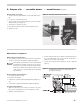
Optional air intake systems
• Combustion air can be piped to the burner from outside if the burner is
ttedwitheitheraBurnerCoverorP/N97406AirIntakeSystem.
• YoumustuseaFieldControlsModelCAS-1CombustionAirSupplyDuct
Kit or equivalent, and install as per kit manufacturer’s instructions and
anyassociatedinstructionsintheBurnerCoveror97406AirIntake
Systeminstructions.
Evenifusingan(optional)airintakesystem,makesurethe
space provides enough ventilation to prevent overheating of
the appliance, burner and controls. The equipment room must
have combustion air/ventilation openings sized large enough
to provide air for cooling the equipment and for combustion
when needed. Failure to comply can result in severe personal
injury, death or substantial property damage.
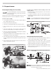
Air piping
Follow all manufacturers’ instructions carefully when install-
ing the air intake duct assembly. Failure to carefully follow all
instructions can result in hazardous operating conditions.
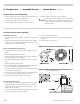
1. InstalltheoptionalairinletadapteriftheburneristtedwithaBurner
Cover.
Airpipingmustbe4-inchdiametermetalorPVC.Installa
4x3reducerattheairadapter(ifusingaburnercover).
2. ConnectairpipingtotheFieldControlsModelCAS-1CombustionAir
SupplyDuctKitandinstallasperFieldControls’instructions.)
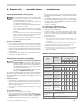
Maximum air piping length
1. USEONLY4-inchairpiping.
2. DO NOT exceed 80 equivalent feet of air piping. NOTE: Install vent
piping as specified in appliance manufacturer’s instructions.
3. Reducemaximimlengthby10equivalentfeetforeachelbowinthe
air piping.
4. Example:Theairpipingcouldconsistof(3)elbows(equals30equivalent
feet)and50feetofstraightpiping;or(4)elbows(equals40equivalent
feet)and40feetofstraightpiping.
Burner adjustments with optional Burner Cover
1. Follow the instructions in this manual for final adjustments to the burner
using combustion test instruments.
2. Oncecombustionisinitiallyset,re-installthecoverandtestagain.If
necessary,removethecoverandreadjusttheburner.Repeattheprocess
until combustion is correct with the cover in place.
3. You must also measure air inlet temperature during start-up to properly
the set combustion. Follow the instructions in this manual.
Burner adjustments with optional Air Intake
System
1. Follow the instructions in this manual andintheAir Intake System
instructions for adjustments to the burner using combustion test
instruments.
2. You must also measure air inlet temperature during start-up to properly
the set combustion. Follow the instructions in this manual.