
User guide

Carlin part number MNEZ123 Rev. 07/13/11
– 22 –
Model EZ-1/2/3 oil burners — Instruction manual
5. Adjustment and verication
Perform combustion test
COMBUSTION MUST BE VERIFIED WITH THE
(OPTIONAL) BURNER COVER IN PLACE —
Removetheburnercoverifinstalled.Setupandadjustthe
burner using the following procedure. Replace the burner
cover,allowtheburner/appliancetorunatleast15minutes,
thencheckcombustionagain.Readjusttheburnerisneces-
sary. The CO
2
will increase when the cover is put on,
particularly if combustion air is piped to the burner.
If air is ducted to an (optional) air adapter,
combustion must be set based on the air inlet
temperature.Airtemperaturevariationswillchangehow
much air enters the burner, so the combustion must be set
to anticipate the variations. Follow the guidelines below.
Adjust burner using test instruments
1. Operateburnerf
or15minutesbeforemakingnaladjustmentsusing
test equipment.
2. Check for leaks in
fuel piping.
Inspectfuelpipingsystemforleaks.Repairanyleakstoavoid
fire hazard from oil leakage or combustion problems due to
air infiltration into oil.
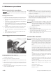
3. Inspectame
• Look at amethrough appliance combustion chamber observation
port.The ame should bewell-dened and should not impinge on
any appliance surface. (If you make air or gas pressure changes later,
inspecttheameagain.)
Donotattempttoconrmcombustionsimplybyinspecting
theamevisually.Youmustusecombustiontestinstruments.
Failure to properly verify/adjust combustion could allow unsafe
operation of the burner, resulting in severe personal injury,
death or substantial property damage.
4. Inserttestprobeintoventorapplianceuedampersampleopening
tosampleueproducts.
Heatingunitsdesignedfornaturaldraftoperationarenormally
set for a slightly negative pressure, usually –0.01 to –0.02
inchesw.c.draftatthecombustionchambertestport.Ap-
pliances designed for forced draft (positive pressure in the
chamber)mustbeair-tighttopreventexltrationofharmful
combustion products. Failure to properly set draft for the
appliance could result in severe personal injury or death.
5. Use combustion test equipment to verify that the burner is properly set
upforyourinstallation.Applianceswithpositivepressureinthechamber
mayrequireawiderairopening.Seeapplianceinstructionsfordetails.
Verify/adjust settings by testing with instruments.
• With the EZ burner equipped with the correct positioning bar, oil nozzle and
initialairbandsetting,theueproductswillusuallycontainbetween11½%
and12½%CO2(5.9%and3.8%O2)andzero(Bacharach)smoke.(Based
onairinlettemperatureof70°F—seeTable5forthepropervaluesat
otherairtemperaturesforburnerswithductedcombustionair.)
• Dependingonlengthofairpiping(whenused)andonairtemperature,CO
2
may change one per cent or more with the cover in place.
• Checksmoke.ItshouldbezeroontheBacharachscale.
• Settheapplianceuedamperorbarometricdraftregulatorsothedraft
or pressure in the vent complies with the appliance manufacturer’s
instructions.
Re-install (optional) burner cover and check
combustion again
1. Allowtheburnertooperatewiththecoveronforatleast15minutes.
(Insert a temperature probe to measure incoming combustion air tem-
peatureifcombustionairisductedtotheburner.)
• RetestCO
2
(orO
2
)andsmokeagain.Thevalueswillchangewhenthecover
isinstalled.Dependingonlengthofairpipingandonairtemperature,CO
2
may change one per cent or more with the cover in place.
• MakesuretheCO
2
(orO
2
)valuesareintherangegiveninTable5forthe
inletairtemperaturemeasured.IFNOT,removethecoverandadjustthe
airbandmoreopentodecreaseCO
2
(increaseO
2
)orclosetheairband
slightlytoincreaseCO
2
(decreaseO
2
).
• Tighten air band clamping screw.
Allinstallationsshouldbecheckedafteronetotwoweeksof
operation to ensure the appliance/burner units are operating
correctly.
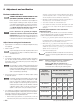
Table 5 Burners using inside air for combustion —
Use “65°F or higher” row in table below.
Burners with ducted combustion air —
MEASURE incoming combustion air temperature
and set the CO
2
(or O
2
)using the following chart:
Incoming
combustion air
temperature
during setup
CO
2
Max and O
2
Min @ setup
No. 2 Fuel oil combustion
CO
2
min CO
2
max O
2
max O
2
min
–20 °F to 0°F
9.6 10.6 7. 8 6.4
5 °F to 30 °F
10.3 11. 3 6.8 5.5
35 °F to 60 °F
10.8 11. 8 6.2 4.8
65 °F or higher
11.5% 12.5 % 5.2% 3.9 %