
User guide

Carlin part number MNEZ123 Rev. 07/13/11
– 12 –
Model EZ-1/2/3 oil burners — Instruction manual
3. Prepare burner (continued)
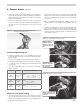
Inspect/install fuel supply
Inspect the oil supply system. Ensure that the fuel lines are
correctlysizedandinstalledandthatthefuelowisunob-
structed,theoiltankiscleanandonly#1or#2heatingoil
aresupplied.Failuretosupplyareliableoilowcouldresult
in loss of heat and potential severe equipment damage.
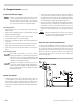
Nozzle line heater
• Oilburners oftenoperateinspaceswheretemperaturestendto be
cool, typically 60°F or lower. Cool oil has higher viscosity, which can
affect atomization, ignition, combustion and fuel consumption. The
nozzle line heater avoids this problem by heating the nozzle line oil to
between 120°F and 130°F, resulting in smoother ignition and improved
combustion.
General guidelines:
• When installing oil lines, use continuous runs of heavy-wall copper
tubing if possible.
• Checkfuelunit(oilpump)datasheetforrecommendedlinesizing,lift
limitations and maximum length.
• Checkallconnectionsandjointstoensuretheyareair-tight.
• Usearettings.DoNOTusecompressionttings.
• Neverusepipesealingtape.Fragmentscanbreakoffandplugfuelline
components.
• Installashut-offvalveatthetankandoneneartheburner.(Usefusible
handledesignvalveswhenpossibleorwhenrequiredbycodes.)
• Installalargecapacityfuellter(ratedfor50micronsorless)nearthe
burner.
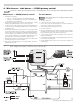
Fuel unit bypass plug
The fuel unit is shipped ready for a one-line oil system
(bypassplugisshippedloose).Installthebypassplugonlyif
connectingtoatwo-lineoilsystem.Operatingwiththeplug
in place on a one-line system will damage the fuel unit and
could lead to oil leakage and fire hazard.
If the fuel line or fuel supply is above burner, never exceed
3 psigpressureatthefuelunitinlet.InstallasuitableOSVto
reducethepressure.Operatingthefuelunitwithhigherinlet
pressure could result in fuel unit seal damage, oil leakage
and potential fire hazard.
• Thenozzlelineheaterneedspowerwhentheburnerisinstandby(no
callforheatfromtheappliance).Makesurethenozzlelineheateris
powered directly from the 120
vacHOTline,notthroughtheappliance
operating control circuit. The nozzle line heater wiring should be shown
on the wiring diagram supplied with the appliance/burner unit.
• Thenozzlelineheaterissuppliedwithanelectricaldisconnectharness,
allowing removal of the combustion head assembly without discon-
necting wires. Position the heater harness disconnect in the rear of
the blower housing, above the blower access cover. The wire leads to
the disconnect route through the side of the housing into the junction
box.
When first starting the burner, or after the service switch has
beenoffforsometime,theheaterrequiresabout15minutes
to bring the oil to operating temperature.
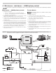
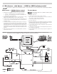
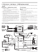
Figure 11 One-line fuel system
One-line fuel system requirements
SeeFigure11.Thestandardburnerfuelunitisasingle-stage,3450-RPM
oilpump.Applythisfuelunitonlyonone-linesystemswherethefuelsup-
ply is on the same level with, or higher than, the burner. This ensures oil
owbygravity.Alsomakesurethetotalliftdoesnotexceed8feet(height
differencefrombottomofoiltanktofuelunit).Forotherconditions,you
must provide a two-line fuel system. You may also have to change the fuel
unit to a two-stage type.