
User guide

Carlin part number MNEZ123 Rev. 07/13/11
– 11 –
Model EZ-1/2/3 oil burners — Instruction manual
3. Prepare burner (continued)
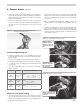
4. Replacetheretentionringassemblybyslippingoneoftherivetedarms
throughthegapbetweentheelectrodetips.Alignthisarmstraightup,
with the ring clamp firmly against the nozzle adapter shoulder. Then
tighten the clamping screw.
5. Checktheelectrodesettings.PositiontheelectrodesasshowninFig-
ure7.Thesesettingsarecriticalinensuringareliableignition.Once
the electrodes are set, check all clamps to be sure they are securely
tightened.
Figure 8 Carefully support the nozzle adapter when
removing or installing nozzle
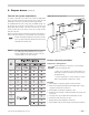
Install head positioning bar
1. The burner is supplied with up to seven calibrated bars that properly
positiontheheadintheairtube.Seethetablebelowforheadposition-
ing bars available.
2. The head positioning bars are stamped with a nozzle size range. Use a
positioning bar with the range that includes the nozzle size installed.
3. SeeFigure9.Removetheexistingbar(ifinstalled)andreplacewith
the correct one.
4. Store any remaining bars in the rearof the burner to allow future
change, if needed.
Model Range Head positioning bars available
EZ-1
EZ-1-HP
0.50 – 1.65
GPH
7 options:
0.50 / 0.60-0.65 / 0.75
0.85-1.00 / 1.10-1.25 /
1.10-1.25 / 1.35-1.50 / 1.65
EZ-2
EZ-2-HP
1.50 – 2.25
GPH
4 options:
1.50 / 1.65-1.75
2.00 / 2.25
EZ-3
EZ-3-HP
2.00 – 2.50
GPH
3 options:
2.00 / 2.25 / 2.50
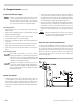
Adjust air band (initial setting)
1. The burner pump pressure is factory set. The pump pressure is indi-
cated on a label affixed to the pump only if it is something other than
100 psi. The air band divisions match the nozzle size regardless of the
pump pressure setting. Loosen the lock screw and move the air band
untilthepointerslineupwiththesettingindicatedintheOEMSet-up
Tableortoasettingthatmatchesthenozzlesize(foraretrotburner).
Seegure10.
2. NOTE:Forhighaltitudeinstallationsabove2,000feet,increasethe
air supply setting 4% for each 1,000 feet above 2,000 feet above sea
level.
3. The burner is now adjusted to the approximate air band setting for the
nozzle size indicated. When you check combustion with instruments
during start-up or servicing, you may have to adjust the air band slightly
toachievethedesiredcombustionreadings.See“Adjustburnerusing
testinstruments,”page22.
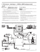
Figure 9 Installing head positioning bar
Remove head bar
retaining screw and
disconnect oil line and
knurled nut from nozzle
line.
Install the head bar
with the correct firing
nozzle size range for
the application.
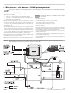
Figure 10 Initial setting of air band
Initially set air band so the
pointer points at the burner
nozzle size.