
User guide

Carlin part number MNEZ123 Rev. 07/13/11
– 10 –
Model EZ-1/2/3 oil burners — Instruction manual
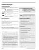
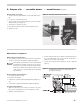
Removing/installing head assembly
Use care when handling burner components after the burner
has been firing. Components can be hot and could cause
severe personal injury.
You will need to remove the combustion head assembly for inspection of the
assembly, replacement of the oil nozzle or adjustment of electrodes.
To remove the assembly:
1. Loosen, and then rotate the two screw clamps securing the ignitor in
place.Swingtheignitorplateopen.
2. Disconnectthenozzlelineheaterharness.
3. Unscrew the oil line fitting and thumb nut at the burner housing.
4. Pull the threaded end of the oil tube into the blower housing (Fig-
ure5).
5. Rotate theassembly 180°so theelectrodes areupside down.This
places the electrode insulators out of the way for easy removal.
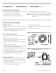
6. Removethecombustionheadassembly,asshowninFigure6,bypulling
the assembly up and out of the housing.
7. Handletheassemblywithcaretoavoidbending/movingtheelectrodes,
or damaging the electrode ceramic insulators.
8. Inspect the gasket on the bottom of the ignitor plate. The gasket prevents
airfromescapingfromthehousing.Replacethegasketifnotingood
condition.
9. Inspect the ignitor contact clips. Clean or replace if necessary to ensure
reliable contact with the electrodes.
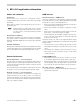
Figure 5 Inserting/removing combustion head assembly
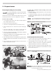
3. Prepare burner
Install nozzle/check electrodes
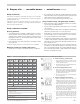
1. Loosentheclampscrewontheretentionringassembly(seeFigure7).
Slidetheretentionringassemblyoffofthenozzleadapter.
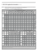
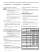
2. Install and tighten the nozzle shown in Table 1, page 4, for retrofit
applications. Install the nozzle given in the appliance manual when
application information for the EZ-1/2/3 oil burner is given.
3. Holdthenozzleadaptersecurelywhenremovingorreplacingthenozzle
(Figure8).Takecarenottodamagetheelectrodeinsulatorsortobend
the electrodes in the process.
Figure 7 Electrode placement, retention ring assembly and
nozzle adapter
Inspect the nozzle adapter before replacing the nozzle. If the
threads have been damaged or shows score marks, replace
the nozzle line/adapter assembly.
To replace the combustion head assembly, reverse the
sequence above.
• Remembertoputtheassemblyinupsidedown,sotheelectrodeinsula-
tors are out of the way.
• SeeFigure6.Youwillhavetolifttheendoftheassemblytoguideit
through the reduced diameter throttle cone at the end of the air tube.
DONOTFORCE.
Use care when tightening the oil line fitting to oil tube extension.
Tighten securely, but do not cross-thread or over-tighten.
Figure 6 Inserting combustion head assembly