
Instruction Manual
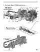

Model 702GAS Advanced gas burners — Instruction manual
Carlin part number MN702G Rev. 03/14/11
– 9 –
Where appliance instructions differ from this manual, follow the appliance instructions.
2. Prepare site • assemble burner • mount burner (continued)
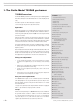
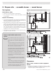
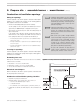
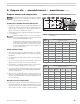
Figure 3 Chamber dimensions & tube configurations
Table 2 Minimum combustion chamber dimensions
(see Figure 3)
High re
input
Refactory combustion chamber applications
(all dimensions in inches)
Gas–MBH
“L” “W” “C” “H”
840 21 15.0 7.5 15
910 23 15.5 8.0 16
966 25 16.0 8.0 16
1092 28 17.0 8.5 17
1218 31 17.5 9.0 18
1330 34 18.0 9.0 18
1456 38 19.0 9.5 19
1600 43 20.0 10.0 20
High re
input
Refactory combustion chamber applications
(all dimensions in inches)
Gas–MBH
“L”
W/ target
“L”
No target
“W” “C” “D”
840 21 25 17.0 8.5 10.5
910 23 27 17.5 9.0 11.0
966 25 29 18.0 9.0 11.0
1092 28 32 19.0 9.5 11.5
1218 31 35 19.5 10.0 12.0
1330 34 38 20.0 10.0 12.0
1456 38 42 21.0 10.5 12.5
1600 43 47 22.0 11.0 13.0
Prepare burner and components
Do not install or operate the burner if any component is damaged
or if burner does not comply with the specifications of Table 2
and other guidelines in this manual.
Combustion chamber minimum dimensions
1. For applications that have not been specifically tested (OEM applications),
verify that the combustion chamber provides the minimum dimensions
shown in Table 2 and Figure 3. For specific OEM applications, the
appliance testing ensures suitability of the chamber.
2. Chamber dimensions may be larger than listed in Table 2, but should not
be excessively large.
Combustion chambers should be sized as recommended in
Table 2. They should be constructed of refractory materials with
the capacity to withstand 2600°F or higher.
It is difficult to include all possible chamber constructions in this
manual. Therefore, you should use the information presented
in this manual combined with commonly practiced techniques
when determining chamber design. If certain conditions are in
question, consult the factory.
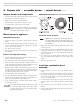
Using chamber linings
1. When using refractory liners or lightweight chambers, use insulating-
type refractory rated 2600°F minimum, or as specified by the appliance
manufacturer.
2. You must install a target wall liner if flame length is close to the length of
the chamber.
3. Use a floor liner when possible. The floor liner will improve firing in most
applications. Extend floor liner 3 to 4 inches up the side walls.
4. Target wall liners — Extend target wall liners at least 3 to 4 inches above
the center of the flame corbel the top 1½ to 2½ inches deep.
5. Use preformed chamber liners when available. Lining the floor and target
wall water-backed combustion chambers with lightweight insulating refrac-
tory will accomplish the same.
6. When converting coal-fired units, install a combustion chamber in the
ashpit area, or fill the ashpit with sand up to 2 inches above the “mud
ring” of the boiler (firing through the door). Install a lightweight refractory
liner on the target wall.
Air tube insertion length (UTL)
1. Usable air tube length (UTL) is the distance from mounting flange to end of
air tube. Verify that the end of the air tube will be flush with, or no more than
¼ inch short of, the inside of the appliance combustion chamber front wall
when the burner is mounted. See Figure 3 for further information.