
Instruction Manual

Model 702GAS Advanced gas burners — Instruction manual
Carlin part number MN702G Rev. 03/14/11
– 14 –
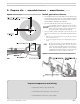
Where appliance instructions differ from this manual, follow the appliance instructions.
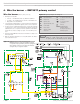
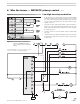
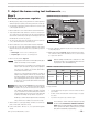
Figure 13 702GAS burners wiring using Honeywell
RM7897C primary control (see appliance manual
or separate wiring information for burner equipped
with a primary control not covered in this manual);
see Figure 12 for a legend to callouts
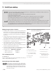
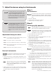
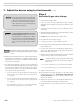
4. Wire the burner — RM7897C primary control
Wire the burner (RM7897C primary control only)
1. All wiring must comply with:
• In the U.S. — the National Electrical Code, ANSI Z223.1/NFPA 54.
• In Canada — the Canadian Electrical Code Part 1, CSA standard C22.1.
• All applicable local codes/standards.
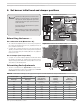
2. Connect the burner following Figures 13, 14 and 15 and any special instructions
or wiring diagrams provided with the appliance, burner or other components.
3. The burner requires a 120 VAC/60 hz/single-phase control power supply, with
a 5-amp fuse. The control circuit current draw is approximately 1.2 amps. An
additional power source is required for the motor (120 VAC or 208-220 VAC,
60 hz), with fuse sized accordingly. See Figure 14 for field wiring connec-
tions.
4. Read the Honeywell RM7897C instructions for information on setting a room
thermostat, if used.
5. Make sure the burner and appliance are correctly wired and the line switch is
properly fused for the load.
Figure 12 Legend for Figures 13 through 15
Turn off power to appliance when servicing burner.
Failure to comply could result in severe person-
al injury, death or substantial property damage.
APS Burner airflow switch
DM Damper motor
HFC High fire control
HL Appliance high limit control
LFS Low fire switch
MC Motor contactor
OC Appliance operating
limit control
TF Combustion head thermal fuse
UV UV sensor
Connector in gas train
junction box
Wire nut
Wires BK=black; BU=blue;
BN=brown; G=green;
O=orange; R=red; V=violet;
W=white; Y=yellow