
Instruction Manual

Model 702GAS Advanced gas burners — Instruction manual
Carlin part number MN702G Rev. 03/14/11
– 13 –
Where appliance instructions differ from this manual, follow the appliance instructions.
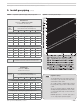
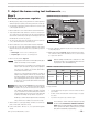
Table 3 Capacities of black iron pipe, cubic feet gas/hour
NATURAL GAS
Capacities in Cubic feet per hour
for Schedule 40 metal pipe
Pipe
size
(inches)
Total length of gas piping,
from meter to burner connection (feet)
20 40 60 80 100
Natural gas @ .60 specic gravity, pressure drop 0.3 in. w.c.
(note 1)
1¼ 730 500 400 350 305
1½ 1,100 760 610 530 460
2 2,100 1,450 1,150 990 870
2½ 3,300 2,300 1,850 1,600 1,400
Natural gas @ .60 specic gravity, pressure drop 0.5 in. w.c.
(note 1)
1¼ 950 660 530 460 400
1½ 1,460 990 810 690 620
2 2,750 1,900 1,520 1,300 1,150
2½ 4,350 3,000 2,400 2,050 1,850
Note 1 For natural gas with specic gravity other than 0.60,
consult National Fuel Gas Code for correction factor.
PROPANE GAS
Capacities in Btuh for
Schedule 40 metal pipe
Pipe size
(inches)
Total length of gas piping,
from meter to burner connection (feet)
20 40 60 80 100
Propane gas @ 1.5 specic gravity, pressure drop 1 psi
½ 1,839 1,264 1,015 869 770
¾ 3,845 2,643 2,122 1,816 1,610
1 7,243 4.978 3,998 3,422 3,033
Propane gas @ 1.5 specic gravity, pressure drop 0.5 in. w.c.
1 787 541 434 372 330
1¼ 1,616 1,111 892 677 543
1½ 2,422 1.664 1,337 1,114 1,014
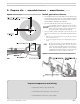
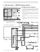
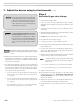
Figure 8 Gas train pressure drop
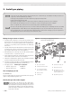
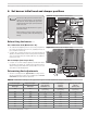
3. Install gas piping (continued)
Regulator spring:
The standard main gas pressure regulator spring (see
item 8, Figure 7, page 12) is plated. The range is from
3.0 to 6.0 inches water column.
The 1” RV61 regulator is available with an optional
blue spring, with a range of 5.0 to 12.0 inches water
column.
The 1¼” or 1½” RV81 regulator is available with the
standard plated spring (3.0 to 6.0 inches water column)
or a violet spring, with a range of 4.0 to 12.0 inches
water column.
PROPANE applications — A brown spring (1.0” to
3.5” w.c. range) may be required for propane.