
Owner's manual


Model 702G/O Advanced gas/oil burners — Instruction manual
Carlin part number MN702GO Rev. 06/23/14
– 9 –
Where appliance instructions differ from this manual, follow the appliance instructions.
2. Prepare site • assemble burner • mount burner (continued)
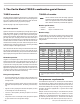
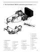
Figure 3 Chamber dimensions & tube congurations
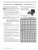
Table 2 Minimum combustion chamber dimensions
(see Figure 3)
Prepare burner and components
Donotinstalloroperatetheburnerifanycomponentisdam-
agedorifburnerdoesnotcomplywiththespecicationsof
Table2andotherguidelinesinthismanual.
Combustion chamber minimum dimensions
1. Forapplicationsthathavenotbeenspecicallytested(OEMapplications),
verifythatthecombustionchamberprovidestheminimumdimensions
showninTable2andFigure3.ForspecicOEMapplications,the
appliancetestingensuressuitabilityofthechamber.
2. ChamberdimensionsmaybelargerthanlistedinTable2,butshould
notbeexcessivelylarge.
Combustionchambersshouldbesizedasrecommendedin
Table2.They shouldbeconstructed ofrefractory materials
withthecapacitytowithstand2600°Forhigher.
Itisdifculttoincludeallpossiblechamberconstructionsinthis
manual.Therefore,youshouldusetheinformationpresented
inthismanualcombinedwithcommonlypracticedtechniques
whendeterminingchamberdesign.Ifcertainconditionsarein
question,consultthefactory.
Using chamber linings
1. When using refractory linersorlightweightchambers, use insulating-
typerefractoryrated2600°Fminimum,orasspeciedbytheappliance
manufacturer.
2.
Youmustinstallatargetwalllinerifamelengthisclosetothelength
ofthechamber.
3. Useaoorlinerwhenpossible.Theoorlinerwillimproveringinmost
applications.Extendoorliner3to4inchesupthesidewalls.
4. Targetwallliners—Extendtargetwalllinersatleast3to4inchesabove
thecenteroftheamecorbelthetop1½to2½inchesdeep.
5. Usepreformedchamberlinerswhenavailable.Liningtheoorandtar-
getwallwater-backedcombustionchamberswithlightweightinsulating
refractorywillaccomplishthesame.
6. Whenconvertingcoal-redunits,installacombustionchamberinthe
ashpitarea,orlltheashpitwithsandupto2inchesabovethe“mud
ring”oftheboiler(ringthroughthedoor).Installalightweightrefractory
lineronthetargetwall.
Air tube insertion length (UTL)
1. Usableairtubelength(UTL)isthedistancefrommountingangetoend
ofairtube.Verifythattheendoftheairtubewillbeushwith,ornomore
than¼inchshortof,theinsideoftheappliancecombustionchamberfront
wallwhentheburnerismounted.SeeFigure3forfurtherinformation.
High fire input
Refactory combustion chamber applications
(all dimensions in inches)
Oil–GPH Gas–MBH “L” “W” “C” “H”
6.00 840 21 15.0 7.5 15
6.50 910 23 15.5 8.0 16
6.90 966 25 16.0 8.0 16
7.80 1092 28 17.0 8.5 17
8.70 1218 31 17.5 9.0 18
9.50 1330 34 18.0 9.0 18
10.40 1456 38 19.0 9.5 19
11.20 1568 43 20.0 10.0 20
High fire input
Refactory combustion chamber applications
(all dimensions in inches)
Oil–GPH Gas–MBH
“L”
W/ target
“L”
No target
“W” “C” “D”
6.00 840 21 25 17.0 8.5 10.5
6.50 910 23 27 17.5 9.0 11.0
6.90 966 25 29 18.0 9.0 11.0
7.80 1092 28 32 19.0 9.5 11.5
8.70 1218 31 35 19.5 10.0 12.0
9.50 1330 34 38 20.0 10.0 12.0
10.40 1456 38 42 21.0 10.5 12.5
11.20 1568 43 47 22.0 11.0 13.0