
Owner's manual


Model 702G/O Advanced gas/oil burners — Instruction manual
Carlin part number MN702GO Rev. 06/23/14
– 24 –
Where appliance instructions differ from this manual, follow the appliance instructions.
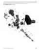
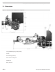
4. Disconnectthe1/4"O.D.copperoilline.
5. Removethetwohousingcoverlockingscrewsandswingthehousingopen.
6. Removethezip-tieholdingtheUVscannercableandairtubethermalfuse
lead.
7. Partially removethe combustion headassembly,and disconnect thetwo
ignitioncablesfromtheelectrodes.
8. Rotatethecombustionheadassembly90°andunscrewthescannerfrom
thesighttube.
9. Disconnectthehightemperaturefuseleads,andremovethecombustion
headassemblyfromthetube.
Thermal fuse
1. Whentheburnerisinahigh-overredraftcondition,andnotproperly
adjusted,itispossiblethattheamecouldashbackinsidetheairtube.
Ifthisoccurs,thethermalfusewillopeninlessthantwoseconds.The
fusemustbereplaced.(Theburnerissuppliedwithsparefuses.)
Annual start-up and service
Thisburnermustbestartedandservicedatleastannually
byaqualiedservicetechnician.Failuretoproperlymaintain
andservicetheburnercouldresultinseverepersonalinjury,
deathorsubstantialpropertydamage.
❏ Discussburner/applianceoperationwithusertodetermineanyproblems
thatmayhaveoccurredduringthepreviousseasonandtoverifyuseris
awareofproperoperationandcareoftheburner/appliance.
❏ Reviewproperoperationoftheappliance/burnerunitwiththeuser.
❏ Turnoffpowertoappliance.
❏ Removecombustionheadassemblytocleanandadjustifnecessary.
(Seeabove.)
❏ Iftheinside surface of theair tube and/or retentionringneed to be
cleaned,cleanthemwithavacuumcleanerwithbrushattachmentwhile
thecombustionheadassemblyisoutoftheburner.
❏ Replacetheoilnozzlewiththecorrectsizespeciedinthismanualor
theOEMguide.Seepage10fortheaccess/replacementprocedure.
❏ Inspectandadjusttheignitionelectrodesandinsulatorsperinstructions
onpage11ofthismanual.Replaceifproperspacingcannotbeachieved
orifcomponentsaredamaged.
❏ Closethehousingcoverplateandsecureinplace.
❏ Inspectthefuellineoillter.Replaceifnecessary.
Oillinelters—Useanon-bypassingltertopreventnozzle
pluggingcausedbypooroilltration.Non-bypassinglters
preventsmallforeignparticlesfrombypassingthelter,a
commonproblem withberelement typelters.Another
problemofsomeltersistheberfromlterelementtears
canbreakawayandplugthenozzleorfuelunit.
❏ Performthecompletecheckoutproceduresofpages18to23,including
systeminspectionandchecks.
❏ Informtheuserofanyproblemsfound.
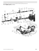
9. Maintenance and service procedures
Turnoffpowertoappliancewhenservicingburner.Afterservic-
ing,always operate burner/applianceto verify allcomponents
arefunctioningcorrectlyandthattheburnerisproperlyadjusted.
Failuretocomplycouldresultinseverepersonalinjury,deathor
substantialpropertydamage.
General maintenance
Cleaning blower wheel
1. Theblowerwheelaccumulatesdustanddebrisfromnormaloperation.You
willneedtocleanthewheelbladesperiodicallytopreventreductioninairow.
Inspecttheblowerwheelregularlybyopeningthehousingcover.
2. Tocleanblades,whennecessary,removetheboltssecuringthemotortothe
blowerhousing.
a. Slidethemotoroutandrotatetoremoveandaccessblowerwheel.
b. Useabrushandvacuumtocleaneachbladeandtheblowerhousing
interior.
c. Installmotor/wheelinblowerhousingandsecurewiththetwobolts.
d. Pushwireslackbackintojunctionbox.
Replacing blower motor or wheel
1. Ifeithertheblowerwheelormotormustbereplaced,removetheboltssecur-
ingthemotortohousing.
2. Disconnectthemotorwiresintheburnerjunctionbox(comingfromtheEZ-
Contactor).
3. LoosentheAllenscrewsecuringtheblowertothemotorshaftandremove
thewheel.
4. Whenassemblingthereplacementassembly,slidethewheelontothemotor
shaftandusefeelergaugestosetspacebetweentheblowerwheelandthe
motorface.Thisspacemustbe3/16inch.
5. Installthemotor/wheelassemblyinthehousing,wirethemotorleadsand
securethemotorwiththetwobolts.
Motor maintenance
• Refertomotormanufacturer’sinstructionsforoilingthemotorasneeded.
Checking ignitor
Nevertestanignitorbyplacingascrewdriver(orothermetallic
object)acrossthe high voltageclips. Thiscould cause ignitor
damageorseverepersonalinjury.
1. Checking41000ignitorsonly:
• Disconnectelectricalpowertoburner.
• Opentheburneraccesscoverandremoveignitorwiresfromtheelec-
trodes.Lightlyclampeachignitorwiretotheburnerhousing,withthe
wireendspointedtowardoneanother,spacedapartbya½"to¾"gap.
• Carefullyenergizeignitorandcheckforsparkarcingatthehighvoltage
terminals.Ifsparkjumpsthegap,ignitorisgood.
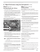
Removing the combustion head assembly
1. Tochecktheelectrodesettingsorchangethenozzle,youmustremove
thecombustionheadassemblyfromtheairtube.Followthestepsbelow,
andreversethesequencetoreassemble.
2. Shutofftheburner.
3. Removethefourgasoricespudsfromthemanifold.