
Owner's manual


Model 702G/O Advanced gas/oil burners — Instruction manual
Carlin part number MN702GO Rev. 06/23/14
– 23 –
Where appliance instructions differ from this manual, follow the appliance instructions.
Step 6 (ring on gas)
Set butterfly gas valve linkage
1. Switchthelow-reswitchtolowre.
2. CheckCO
2
andCO.TheCO
2
shouldbebetween9.0%and10.0%(natural
gas)orbetween10.0%and11.2%(propane);withCOlessthan100PPM.
3. Toadjustthelow-reair(changeCO
2
),movetheburnerfuelselector
switchtoOFF.Adjust the buttery gasvalvelinkageas described in
thefollowingtochangethelow-regasowtotheburnerhead.Donot
changethemaingaspressureregulatorsetting.
4. DO NOT ADJUST THE LOW-FIRE AIR DAMPER SETTING.Thismust
beleftassetforoilring.
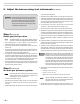
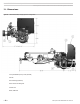
5. SeeFigure18forlocationoflinkagecomponents.
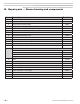
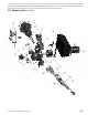
Figure 18 Buttery gas valve linkage
6. Raisethedampermotorlinkagebypullinguponthedamperlinkage
locknutandholdinthisposition.
7. Loosenthetwohexheadscrewsonthebutteryvalvelinkagearmboss.
Thenlowerthedamperlinkagetothelowrepositionwiththedamper
linkagelocknut.Releasethelocknut.
8. Markthepositionofthebutteryvalvelinkagearmswiveljointlocknut
withapencilorfelt-tippen.Thenloosentheswiveljointlocknut.
Toadjustthelinkage,movetheswiveljointlocknutinsmall
increments.A1/8-inchmovecancauseCO
2
tochangeas
muchas1.5%.
• Ifmoregasisneeded(toincreaseCO
2
),movetheswiveljointtotheRIGHT.
• Iflessgasisneeded(todecreaseCO
2,
),movetheswiveljointtotheLEFT.
9. Tightentheswiveljointinplace.
10.Raisethedampermotorlinkagebypullinguponthedamperlinkage
locknutandholdinthisposition.The buttery valve shaft slot must
be horizontal
.Ifnot,useacommon-bitscrewdrivertorotatethevalve
slottohorizontal.
11.Tightenthetwohexheadscrewsonthebutteryvalvelinkagearmboss.
Thenlowerthedampermotorlinkagetothelowreposition.
12.RestartandrepeatasnecessaryuntilCO
2
andCOareacceptable.
8. Adjust the burner using test instruments (continued)
Step 7 (ring on oil and on gas)
Verify operation
Burner/appliance/controls operation
❏ Testoperatingandlimitcontrolsonapplianceasspeciedinappliance
instructions.
❏ Checkoperationoftheprimarycontrolbyforcinglockouttooccur.For
primarycontrolsthatenterlatch-upaftermultiplelockouts,forcelatch-up
tooccuraswell.Resetprimarycontrolpercontroldatasheetinstructions
aftereachtest.
❏ Startandstoptheburnerseveraltimes,allowingtheprimarycontrolto
sequencethroughnormaloperation.Verifycorrectoperationofburner
andprimarycontrolthroughoutonbothoilandgas.
❏ Conrmand/oradjustoverrecombustionpressureforoilandgasopera-
tion.Refertoboiler/furnacemanufacturer’srecommendations.
Verify vent system operation
❏ Verifyventisoperatingcorrectlyandueproductsareproperlyexhausted
frombuilding.Ifthebuildingcontainsanyexhaustfansorconditionsthat
couldaffectvent performance,checkburner/appliance/ventoperation
withexhaustfans(orotherconditions)operating.
Combustion/ventilation air
❏ Verifycombustion/ventilationairopeningsarenot,andwillnotbeob-
structed.
❏ Verifyairopeninglouversarefullyopen.
❏ Iflouversaremotor-operated,verifymotorandendswitchareinterlocked
withappliance/burnerwiringtopreventoperationoftheburneriftheair
louversarenotfullyopened.
Prepare burner for normal operation
❏ Cycleburneroffwithappliancecontrols.
❏ Turnoffpowertotheappliance.
❏ Sealtheapplianceuetestopening.
❏ Verify all componentsand wires arein placeandburner isreadyfor
operation.
❏ Restorepowertotheappliance.
Train the user
❏ Traintheusertooperatetheburnerandapplianceundernormalcondi-
tions.
❏ Explaintheproceduretoshutdowntheburner/appliancewhenrequired.
❏ Reviewthebackcoverofthismanual(andtheappliancemanual)with
theuser.
❏ Verifytheuserisawareofallproceduresspeciedinthemanuals.
❏ Verifythattheuserwillnotstoreorusecombustibleliquidsormaterials
orcontaminantsinthevicinityoftheburner/appliance.