
Owner's manual

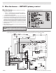
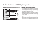


Model 702G/O Advanced gas/oil burners — Instruction manual
Carlin part number MN702GO Rev. 06/23/14
– 20 –
Where appliance instructions differ from this manual, follow the appliance instructions.
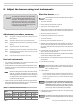
Adjustment procedure, summary
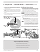
Step 1: Sethigh-reoilairowby adjustingthecombustion head.See
detailsfollowing.
Step 2: Adjusttheairdamperforlow-reoil.Seedetailsfollowing.
Step 3: Adjustthedampermotorendswitch(onlyifnecessary).Seedetails
following.
Step 4: Setgaspilotoperation.Seedetailsfollowing.
Step 5: Sethigh-regasowtomatchhigh-reair.Seedetailsfollowing.
Step 6: Adjustthebutteryvalvelinkagetomatchlow-regastolow-re
air.Seedetailsfollowing.
Step 7: Verifyoperationofburner,appliance,andcontrols.
Use test instruments
1. Use combustiontestequipment andanaccurate manometeror draft
gaugetocorrectlysettheburnerasrequired.
2. Overrepressuremustnotexceedtheappliancemanufacturer’srecom-
mendations.Theburnermustneverberedatanoverrepressuremore
than0.60inchesw.c.
Whentheoverrepressureispositive,themaximumburner
ringrateisreduced.Theringrateis also reduced for
altitudeshigherthan2000feetabovesealevel.Seepage3
forratinginformation.Ensurethattheoilnozzleselectedis
correcttherequiredringrate.
3. Adjusttheburnerfuelandairsettingsusingthefollowingprocedures.
Whenadjustmenthasbeencompleted,theCO
2
(orO
2
)shouldbewithin
therangesinTable6,atbothlowreandhighre.
Table 6 Allowable values of CO
2
and O
2
Fuel
CO2 O2
Minimum Maximum Maximum Minimum
#2 Fuel Oil 10.5 % 12.5 % 6.6 % 3.9 %
Natural Gas 8.5 % 10.0 % 6.2 % 3.6 %
Propane 9.5 % 11. 2 % 6.0 % 3.5 %
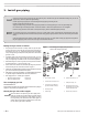
8. Adjust the burner using test instruments
ThesettingsgiveninSection7areinitialsettings
only. You must use test instrumentstocheck
combustion,andadjusttheburnerasnecessary,
followingtheproceduresgiveninthefollowing
pagesofthismanual.Failuretoproperlyadjustthe
burnercanresultinseverepersonalinjury,death
orsubstantialpropertydamage.
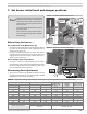
Start the burner (ringonoil)
Donotstarttheburnerifthecombustionchambercontains
oiloroilvapor.
1. TurnserviceswitchOFF.
2. Performinspectionsandcheckoutsonpage18.
3. Verifyburnerissetaccordingtopage19.
4. Sliponeendofa3/16-inchI.D.clearplastichoseovertheendofthefuel
unitbleedvalve,theotherendintoacontainer.Thenopenbleedvalve.
5. SetburnerfuelselectorswitchtoOIL.
6. Setthermostat(operatingcontrols)tocallforheat.
7. TurnserviceswitchON.
8. Burnermotor,fuelunitandblowershouldturnon.
9. Bleedtheoillineuntiltheplasticlineisfreeofbubbles;thenanother15
secondslonger.(Shouldtheprimarycontroltimingcausealockoutdur-
ingpurging,restarttheburnerfollowingtheprimarycontroldatasheet
instructions.)
10.
Closethebleedvalve.Theburnershouldcyclethroughthesequence
givenintheprimarycontroldatasheet.
11.Shouldcontrol/burnerfailtooperatecorrectly,shutburneroffimmediately
andcheckburnersettingsandfuelsupplies.
12.Operateburnerfor15minutesbeforemakingnaladjustmentsusing
testequipment.
13.Checkforleaksinfuelpiping.
Inspectfuelpipingsystemforleaks.Repairanyleaksto
avoidrehazardfromoilleakageorcombustionproblems
duetoairinltrationintooil.
14.Inspecttheame
• Lookattheamethroughtheappliancecombustionchamberobserva-
tionport,ifavailable.Theameshouldbewell-denedandshouldnot
impingeonanyappliancesurface.(Ifyoumakeairchangeslater,inspect
theameagain.)
Do not attempt to conrm combustion simply by inspect-
ing the ame visually. You must use combustion test
instruments.Failuretoproperlyverify/adjustcombustion
couldallowunsafeoperationoftheburner,resultinginsevere
personalinjury,deathorsubstantialpropertydamage.
15.Insertthecombustionequipmenttestprobeintoaventsampleopening
tosampleueproducts.
Allinstallationsshouldbecheckedafteronetotwoweeksof
operationtoensuretheappliance/burnerunitsareoperating
correctly.