
Owner's manual


Model 702G/O Advanced gas/oil burners — Instruction manual
Carlin part number MN702GO Rev. 06/23/14
– 12 –
Where appliance instructions differ from this manual, follow the appliance instructions.
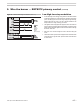
3. Install gas piping
Piping from gas meter to burner
1. Verifythegastrainontheburneriscorrectlysized.Thegastrainpres-
suredropmustnotbemorethanthegaspressureattheburnergas
trainentranceminus3.4"w.c.(pressurerequiredatentrancetobuttery
valve).SeeFigure8forgastrainpressuredropinformation.Thestandard
gastrainis1inch.
2. Ifpossible,installanewgaslinedirectlyfromthegasmeter.Ifyouare
usinganexistinggasline,verifyitiscleanandingoodcondition,and
verifyitislargeenoughtohandletheloadofallconnectedappliances.
3. Whenbranchingfromacommongasline,donottapofffromthebottom
ofhorizontalsections—onlyfromthesideortop.
4. Installamainmanualshutoffvalve,sedimenttrapandgroundjointunion
neartheburnergastrainconnectionasshowninFigure7.
5. Iftheburnerisinstalledinsideanappliancejacket,installthemainmanual
gasvalveandsedimenttrapexternaltothejacket.
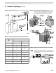
6. Sizepiping(orverifysize)usingTable3.Youwillndadditionalinformation
ongaslinesizingintheNationalFuelGasCode,ANSIZ223.1.
7. Gassupplypressure—naturalgasorpropane
• Maximumsupplypressure: 14inchesw.c.
• Minimumsupplypressure: 5inchesw.c.
Test and purge gas line
ReadWARNINGabove.
Pressuretestandpurgetheline.Pressuretestingshouldbedonebythegas
supplierorutility,followingallapplicablecodes.
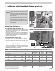
Check pilot gas line orifice nipple
Check thelabelon the pilot linegasoricenipple(item1,
page29).Thelabelontheoricenipplemustagreewiththe
gasused(naturalorpropanegas).Ifthenippleisnotcorrect
forthegasbeingused,obtainthecorrectoricenippleand
replace.Makesurethenippleisinstalledinthecorrectdirec-
tion,asshownbythearrowonthelabel.
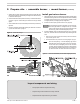
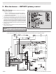
Figure 7 Connecting gas supply piping to burner
(shown with straight gas train)
1 Pipetometerorbranch
2 T-handlemainmanualgasvalve
3 Useclean,burr-freeblackiron
pipeandmalleableironttings
4 Groundjointunion
5 Sedimentleg
6 Upstreampressuretap,1/4"
7 Outletpressuretap,1/4"
8 Gasregulatoraccessscrew
(theregulatorspringislocated
undertheadjustingscrew)
9 Gastrainwirejunctionbox
Connectfromthegassupplytotheburnergastraininletusingnew,cleanblackironpipeandmalleableironttingsonly.Donotuse
copper,brass,castironorgalvanizedpipeorttings.
Providesupportforgaspiping.Donotresttheweightofthegaspipingonburnergastrain.
Provideasupportfortheburnergastrain.
Applypipedopesparinglyatalljoints.Useonlypipedopelistedforusewithpropanegas.Donotusepipesealingtape.
Donotholdthegasvalvewithpipewrench.Usecrescentwrenchorothersmooth-jaweddevice.Donotovertighten.
Failuretocomplywithabovecouldresultinseverepersonalinjury,deathorsubstantialpropertydamage.
Donotexposethegastraintogaspressureinexcessof14incheswatercolumn.Higherpressurecoulddamagethevalveseat,
resultinginpotentiallyhazardouscondition.Whenpressuretestingpipingathigherpressures,disconnectburnerfromgaslinebefore
testing.
Ifthegassupplypressurecanexceed14incheswatercolumnatanytime,youmustinstallalockuptypegaspressureregulatorin
thegassupplypiping,aheadofthemainmanualgasvalveinstalledattheburner.