
Owner's manual
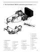


Model 702G/O Advanced gas/oil burners — Instruction manual
Carlin part number MN702GO Rev. 06/23/14
– 10 –
Where appliance instructions differ from this manual, follow the appliance instructions.
Inspect burner and components
• Checktheairtubelength.VerifytheusablelengthofthetubeUTLwill
belongenough(see“Mountburnerinappliance”).
• Visuallyinspectallburnercomponentsandwiring.
• Verifythatwiringisintactandleadsaresecurelyconnected.
• Verifythatallburnercomponentsareingoodcondition.
Donotinstallor operatetheburnerifanycomponentis
damagedorifburnerdoesnotcomplywithotherguidelines
ofthismanualandtheappliancemanual.
Mount burner in appliance
Welded-flange burners
1. Verify the boltpatternon the appliance chambermatches the ange
pattern.
2.
Verify the insertion depth (UTL) matches thedepthof the appliance
opening(sotheendoftheairtubeisushwith,orslightlyshortof,the
insidesurfaceofthecombustionchamber).
3. Placegasketontoboilerfrontplate.
4. Slidetheendoftheairtubeintotheopeningandsecuretheangeto
theboilerfrontplate.
Burners with adjustable flanges
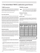
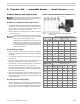
1. Verifytheangemountingslotswilllineupwiththeappliancebolts.(See
Figure4foradjustableangedimensions.)
2. Placetheangegasketinpositionontheappliancemountingplate.
3. Measurethedistancefromtheinsideofthecombustionchambertothe
outsideoftheappliancemountingplate.Slidetheadjustableangeon
theairtubeuntilitisthisdistancefromtheendoftheairtube.
4. Markthispositionoftheangeontheairtubewithapencilorpensoyou
canverifytheangeiscorrectlypositionedasyoucompletetheinstalla-
tion.Theendoftheairtubemustbeush,oralmostush,withtheinside
ofthecombustionchamberwall.(SeeFigure3,page9)
5. Tightentheangelockingscrewsngertight.
6. Inserttheairtube/angeassemblyintotheapplianceopening.(Rotate
theangeifneededtoalignwiththemountingbolts.)Securetheange
totheappliancefrontplate.
7. Seethefollowinginstructionstoinstalltheburnerpedestal,neededto
properlysupporttheburner.
Aforceddraftadjustableangemustbesealedtotheair
tubetopreventpossibleleakageofueproducts.Failure
tocomplycouldresultinseverepersonalinjury,deathor
substantialpropertydamage.
Figure 4 Adjustable ange
2. Prepare site • assemble burner • mount burner (continued)
Install the burner pedestal
702G/Oburnerssuppliedwithanadjustableangearealso
suppliedwithapedestalforsupporting the burner. (The
pedestalisavailableasanoptionforaburnerequipped
withaweldedange.)
1. Adjustthepedestalsothattheheightoftheairtubematchesthelocation
oftheburneropening.
2. Thepedestalhasapproximately3"ofadjustment.Iftheburneropening
istoohighforthepedestaltorestontheoor,thenconstructabase.
Twosolidcementblocks,sidebyside,isrecommended.Alternatethe
directionaslayersareputdown.
3. Placeaspiritlevelontheairtube.Adjustthepedestalsotheairtube
slopesdownslightlytowardtheappliance.Theslopeshouldbeabout
2degrees.
4. Tightenthepedestalboltsecurely.
Install the oil nozzle
1. Follow the instructions on page24to remove the combustion head
assembly.
2.
Installandtightenthenozzlelistedintheapplianceinstructionmanualor
theCarlinOEMSpecGuide.Ifnozzleinformationisnotavailable,begin
withthenozzlelistedonpage4.(Youmayhavetochangethenozzle
laterifcombustionresultsarenotacceptable.)
3. Slidetheamescannersightpipeassemblytotherearbylooseningthe
1/8”Allenscrewontheholdingbase.
4. Holdthenozzleadaptersecurelywhenremovingorreplacingthenozzle.
Takecarenottodamagetheelectrodeinsulatorsortobendtheelectrodes
intheprocess.
Inspectthenozzleadapterbeforereplacingthenozzle.Ifthe
threadshavebeendamagedorshowscoremarks,replace
thenozzleline/adapterassembly.