™ Instruction manual Except where specifically stated otherwise, this manual must be used only by a qualified service technician. In the state of Massachusetts, this product must be installed by a licensed Plumber or Gas Fitter. Failure to comply with the above or other requirements in this manual could result in severe personal injury, death or substantial property damage. USER — Refer only to User care and maintenance on back page for information regarding operation of this burner.
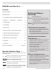
Model 702G/O Advanced gas/oil burners — Instruction manual Where appliance instructions differ from this manual, follow the appliance instructions. PLEASE read this first . . . Contents PLEASE read this first..................................................................2 General information......................................................................3 Before installing or servicing: Should overheating occur: (1) Shut off the oil and gas supplies to the burner.
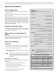
Model 702G/O Advanced gas/oil burners — Instruction manual Where appliance instructions differ from this manual, follow the appliance instructions. General information Burner applications Follow all instructions in this manual, the primary control data sheet and the appliance manual. Verify the burner is correct for the appliance being used and for all applicable codes/standards.
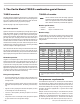
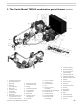
Model 702G/O Advanced gas/oil burners — Instruction manual Where appliance instructions differ from this manual, follow the appliance instructions. 1. The Carlin Model 702G/O combination gas/oil burner 702G/O overview 702G/O oil nozzles The Model 702G/O combination gas/oil burner is a low-high-low (step modulating) burner that utilizes a damper motor to control air (and gas fuel rate). Fuel is selected using the Gas/oil changeover switch.
Model 702G/O Advanced gas/oil burners — Instruction manual Where appliance instructions differ from this manual, follow the appliance instructions. 1.
Model 702G/O Advanced gas/oil burners — Instruction manual Where appliance instructions differ from this manual, follow the appliance instructions. 2. Prepare site • assemble burner • mount burner Vent system Figure 1 Vent and vent connector installations, typical Vent/chimney sizing 1. Follow all local codes when sizing the vent and chimney. 2. Refer to the appliance manufacturer’s manual, when available, for venting recommendations. Prepare vent/chimney 1.
Model 702G/O Advanced gas/oil burners — Instruction manual Where appliance instructions differ from this manual, follow the appliance instructions. 2. Prepare site • assemble burner • mount burner (continued) Combustion air/ventilation openings Installing the burner/appliance in a space that does not provide enough air for combustion and ventilation can result in severe personal injury, death or substantial property damage.
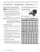
Model 702G/O Advanced gas/oil burners — Instruction manual Where appliance instructions differ from this manual, follow the appliance instructions. 2. Prepare site • assemble burner • mount burner (continued) Prepare the appliance Burner input: Install a burner sized for the normal input rating of the appliance. Do not install a burner with a higher firing rate than the appliance rating. Do not install a burner with a firing rate more than 10% lower than the appliance rating.
Model 702G/O Advanced gas/oil burners — Instruction manual Where appliance instructions differ from this manual, follow the appliance instructions. 2.
Model 702G/O Advanced gas/oil burners — Instruction manual Where appliance instructions differ from this manual, follow the appliance instructions. 2. Prepare site • assemble burner • mount burner Inspect burner and components • Check the air tube length. Verify the usable length of the tube UTL will be long enough (see “Mount burner in appliance”). • Visually inspect all burner components and wiring. • Verify that wiring is intact and leads are securely connected.
Model 702G/O Advanced gas/oil burners — Instruction manual Where appliance instructions differ from this manual, follow the appliance instructions. 2. Prepare site • assemble burner • mount burner 5. Slide the flame scanner sight pipe assembly forward until the 3/8" pipe fits against the retention ring assembly. Then tighten the 1/8" Allen screw to secure the tube in place. 6. Check the electrodes and reposition if necessary. Position the electrodes as shown in Figure 5.
Model 702G/O Advanced gas/oil burners — Instruction manual Where appliance instructions differ from this manual, follow the appliance instructions. 3. Install gas piping Connect from the gas supply to the burner gas train inlet using new, clean black iron pipe and malleable iron fittings only. Do not use copper, brass, cast iron or galvanized pipe or fittings. Provide support for gas piping. Do not rest the weight of the gas piping on burner gas train. Provide a support for the burner gas train.
Model 702G/O Advanced gas/oil burners — Instruction manual Where appliance instructions differ from this manual, follow the appliance instructions. 3. Install gas piping (continued) Capacities of black iron pipe, cubic feet gas/hour Table 3 Figure 8 Gas train pressure drop NATURAL GAS Capacities in Cubic feet per hour for Schedule 40 metal pipe Pipe size (inches) Total length of gas piping, from meter to burner connection (feet) 20 40 60 80 100 Natural gas @ .
Model 702G/O Advanced gas/oil burners — Instruction manual Where appliance instructions differ from this manual, follow the appliance instructions. 4. Install oil piping Inspect/install fuel supply Use two-line oil piping only The fuel unit must be connected to a two-line fuel system to ensure oil flow through the pump during gas operation. This is needed to keep the pump cool and lubricated. Failure to protect the pump can result in early pump failure.
Model 702G/O Advanced gas/oil burners — Instruction manual Where appliance instructions differ from this manual, follow the appliance instructions. 4.
Model 702G/O Advanced gas/oil burners — Instruction manual Where appliance instructions differ from this manual, follow the appliance instructions. 5. Wire the burner — RM7897C primary control Wire the burner (RM7895C or RM7897C primary control only) 1. All wiring must comply with: Figure 12 Legend for Figures 13 and 14 In the U.S. — the National Electrical Code, ANSI Z223.1/NFPA 54. In Canada — the Canadian Electrical Code Part 1, CSA standard C22.1. • All applicable local codes/standards.
Model 702G/O Advanced gas/oil burners — Instruction manual Where appliance instructions differ from this manual, follow the appliance instructions. 5. Wire the burner — RM7897C primary control Figure 14 702G/O field wiring connections (RM7897C only) (continued) Low-High-Low step modulation 1. To take advantage of the energy-saving potential of the Model 702G/O combination gas/oil burner, it should be wired to operate at low-high-low cycles.
Model 702G/O Advanced gas/oil burners — Instruction manual Where appliance instructions differ from this manual, follow the appliance instructions. 6. Checkout procedure — before starting the burner Before firing the burner . . . Should overheating or an emergency occur, immediately do the following: • Shut off oil supply line and gas supply valves. • Under some circumstances power should remain on for water pumps or blowers. Determine proper response before attempting start-up.
Model 702G/O Advanced gas/oil burners — Instruction manual Where appliance instructions differ from this manual, follow the appliance instructions. 7. Set burner initial head and damper positions Figure 16 Set initial combustion head position Follow the procedures given here and on the following pages to ensure the burner is correctly adjusted. Take your time and the results in both gas and oil modes should result in good operation, and avoid return service calls.
Model 702G/O Advanced gas/oil burners — Instruction manual Where appliance instructions differ from this manual, follow the appliance instructions. 8. Adjust the burner using test instruments Start the burner The settings given in Section 7 are initial settings only. You must use test instruments to check combustion, and adjust the burner as necessary, following the procedures given in the following pages of this manual.
Model 702G/O Advanced gas/oil burners — Instruction manual Where appliance instructions differ from this manual, follow the appliance instructions. 8. Adjust the burner using test instruments The linkage between the damper motor arm and the air damper crank is set at the factory, and should ONLY need adjustment if the damper motor or the damper rod is replaced. With the burner in high-fire position, there should be minimal play in the connecting rod. DO NOT change this linkage setting. (continued) 3.
Model 702G/O Advanced gas/oil burners — Instruction manual Where appliance instructions differ from this manual, follow the appliance instructions. 8. Adjust the burner using test instruments (continued) is still strong with main flame on. Smell around the gas train and check all joints with a soap suds mixture to ensure the gas train and all components are tight and leak-free. Shut down the burner and correct any leak immediately.
Model 702G/O Advanced gas/oil burners — Instruction manual Where appliance instructions differ from this manual, follow the appliance instructions. 8. Adjust the burner using test instruments Step 6 (firing on gas) Step 7 (continued) (firing on oil and on gas) Set butterfly gas valve linkage Verify operation 1. Switch the low-fire switch to low fire. Burner/appliance/controls operation 2. Check CO2 and CO. The CO2 should be between 9.0% and 10.0% (natural gas) or between 10.0% and 11.
Model 702G/O Advanced gas/oil burners — Instruction manual Where appliance instructions differ from this manual, follow the appliance instructions. 9. Maintenance and service procedures Turn off power to appliance when servicing burner. After servicing, always operate burner/appliance to verify all components are functioning correctly and that the burner is properly adjusted. Failure to comply could result in severe personal injury, death or substantial property damage.
Model 702G/O Advanced gas/oil burners — Instruction manual Where appliance instructions differ from this manual, follow the appliance instructions. 9.
Model 702G/O Advanced gas/oil burners — Instruction manual Where appliance instructions differ from this manual, follow the appliance instructions. For parts not shown or listed, contact factory and/or check separate documentation supplied with appliance/burner unit. 10. Repair parts — Burner housing and components Item Description Part No.
Model 702G/O Advanced gas/oil burners — Instruction manual Where appliance instructions differ from this manual, follow the appliance instructions. For parts not shown or listed, contact factory and/or check separate documentation supplied with appliance/burner unit. 10. Repair parts (continued) Carlin part number MN702GO Rev.
Model 702G/O Advanced gas/oil burners — Instruction manual Where appliance instructions differ from this manual, follow the appliance instructions. For parts not shown or listed, contact factory and/or check separate documentation supplied with appliance/burner unit. 10. Repair parts — gas train components Item Description Part No.
Model 702G/O Advanced gas/oil burners — Instruction manual Where appliance instructions differ from this manual, follow the appliance instructions. For parts not shown or listed, contact factory and/or check separate documentation supplied with appliance/burner unit. 10. Repair parts (continued) Carlin part number MN702GO Rev.
Model 702G/O Advanced gas/oil burners — Instruction manual Where appliance instructions differ from this manual, follow the appliance instructions. 11. Dimensions Figure 19 Dimensional data, straight gas train configuration 1 Honeywell R7897C primary control (standard) 2 Air tube 3 Universal flange (standard) 4 Carlin 41000 solid state ignitor 5 Junction box 6 Motor, 48N-frame – 30 – Carlin part number MN702GO Rev.
Model 702G/O Advanced gas/oil burners — Instruction manual Where appliance instructions differ from this manual, follow the appliance instructions. 11. Dimensions Figure 20 (continued) Dimensional data, angled gas train configuration 1 Honeywell R7897C primary control (standard) 2 Air tube 3 Universal flange (standard) 4 Carlin 41000 solid state ignitor 5 Junction box 6 Motor, 48N-frame Carlin part number MN702GO Rev.
Model 702G/O Advanced gas/oil burners — Instruction manual Where appliance instructions differ from this manual, follow the appliance instructions. 702G/O burner User care and maintenance Refer only to the information on this page, intended for your use. The remainder of this manual is intended only for your service technician. Failure to comply could result in severe personal injury, death or substantial property damage. For other than routine maintenance, contact a qualified service company.