
Owner manual

Model 601GAS burner — Instruction manual — Supplement – Massachusetts Code
Carlin part number MN601GASM Rev. 05/01/07
– 2 –
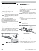
Where appliance instructions differ from this manual, follow the appliance instructions.
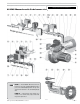
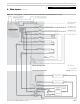
601GAS Massachusetts Code burner at-a-glance . . .
1 Manual gas valve (with two test tappings)
Gas supply entrance (gas train size): — 1” NPT or 1¼” NPT
(gas train size depends on input and application)
Supply pressure: 5” w.c. min; 14” w.c. max; natural gas or propane
2 Gas pressure regulator
3 Gas pressure regulator vent port (fitted with fixed orifice; vent to outside where
required by applicable codes)
4 Low gas pressure switch — manual reset
5 Automatic gas valve
6 Junction box with terminal strip
7 Automatic gas valve (two-stage regulating diaphragm valve)
9 High gas pressure switch — manual reset
10 Manual gas valve
10a Burner gas manifold pressure test port, 1/4” NPT
11 Union
12 Orifice nipple (burner gas orifice plug located inside)
13 Burner gas connection, 1” or 1¼” NPT
14 Air tube (flange omitted for clarity), with powder coat paint finish
15 Flame rod/insulator assembly
16 Combustion head assembly
17 Gas saddle connection gasket
18 Gas manifold
19 Ignition electrode/insulator assemblies
20 Motor (with permanently-lubricated bearings and thermal overload protection)
21 Hinged burner flange door — for access and removal of combustion head/gas
manifold assembly
22 Ignitor (Carlin Model 41000 solid state electronic ignitor — 14,000 volts, continu-
ous duty rated)
23 Hinged cover plate (for access to blower wheel & electrodes)
24 Airflow proving switch — Prevents burner from firing if air is not moving
25 Air damper — Only a single adjustment required for setting combustion air; see
page 9 for starting setting based on input
26 Door interlock switch — prevents burner operation if flanged door is open
27 Primary control — Carlin Model 60200FR microprocessor-based interrupted
ignition flame supervisory control (flame rectification); Flame current test jack is
located to right of control terminal strip
28 Burner junction box (installer electrical entrance)
29 Time delay relay (8-second)
Replace Instruction manual content:
This page replaces Instruction manual page 4.