
Instruction Manual

Model 301GAS burner — Instruction manual
Carlin part number MN301GAS Rev. 03/14/11
– 9 –
Where appliance instructions differ from this manual, follow the appliance instructions.
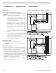
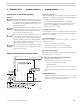
Mount burner in appliance
• Verifyapplianceburnerfrontplatedimensionsandboltlocations.
• Slidegasketsuppliedwithburneroverendofairtube.
• Insertburnerintoapplianceopeningandboltinplace.
• Levelthehousingifnecessarybylooseningthesetscrewssecuringthe
housing to the air tube. Retighten the set screws.
Inspect components and wiring
• Visuallyinspectallburnercomponentsandwiring.
• Verifythatwiringisintactandleadsaresecurelyconnected.
• Verifythatallburnercomponentsareingoodcondition.
• Checkgaspressureswitchsettings.Setthelowgaspressureswitchat
manifold setting minus 50%. Set the high gas pressure switch at manifold
setting plus 50%.
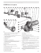
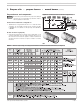
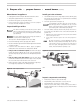
Figure 8 Gas orifice location
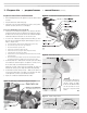
Install gas train on burner
1. The standard burner gas train is shipped fully assembled, with the piping
disconnected at the gas train union. See separate instructions if installing
an optional knocked down gas train.
2. Connect the gas train at the union (Figure 9).
To avoid damage to gas train components, do not hold compo-
nents with a pipe wrench or overtighten. Use only a crescent
wrench or other means. Failure to comply could result in severe
personal injury, death or substantial property damage.
3. Connect the flexible conduit, pre-attached to the primary control J-box, to
the gas train J-box, and attach the wires to the terminal strip inside the
gas train J-box.
a. Match wire colors of the incoming wires to those pre-wired to the terminal
strip inside the gas train J-box.
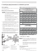
b. See the label in the burner junction box or the wiring diagram on
page 11.
Gas valve vent opening —TheV48 diaphragm gas valve is
fitted with a factory-installed vent liminting orifice in the vent
connection.Donotremoveorchangethesizeofthisorice.If
local codes require, install piping from the vent connection to
outside, sized and installed as required by codes.
Figure 9 Gas train installation
Inspect/redrill gas orifice
If the burner is installed, you must disconnect power to burner
and close main manual gas valve before proceeding. Failure to
do so could result in severe personal injury, death or substantial
property damage.
In the state of Massachusetts, when lever-type gas shutoffs are
used, they must be T-handle type only.
1. Turnoffpowertotheburner/appliancebeforeproceeding.
2. Close main manual gas valve in gas supply line to burner.
3. Disconnecttheburnergastrainunioniftheburner/gastrainisinstalled.
See Figures 8 and 9.
4. Locate the correct orifice drill size in Table 1, page 7 (or appliance
manual). Then check actual orifice size using that size drill bit.
5. If the gas orifice is smaller than required, unscrew the orifice nipple
from the elbow. Then redrill the orifice to the correct size. Replace the
gas train, using only pipe dope listed for use with liquefied petroleum
gases.
6. If the gas orifice is larger than required, remove the orifice nipple
from the elbow. Obtain a replacement orifice nipple. If necessary, drill
the correct orifice hole in the new orifice to the correct size.
7. Replace gas train. Seal pipe joints with a small amount of pipe dope.
Use only pipe dope approved for use with propane gas.
1. Prepare site • prepare burner • mount burner (continued)