
Instruction Manual

Model 301GAS burner — Instruction manual
Carlin part number MN301GAS Rev. 03/14/11
– 8 –
Where appliance instructions differ from this manual, follow the appliance instructions.
1. Prepare site • prepare burner • mount burner (continued)
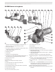
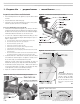
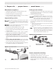
Figure 5 Combustion head/manifold assembly
Figure 4 Removing combustion head/gas manifold
Inspect/correct flame rod/electrode
• Beforeinstallingtheburnerintheappliance,inspecttheamerodand
electrode.
• Verifythedimensionsshowninthispage.
• Iftheamerodorelectrodeisdamagedornotinthecorrectposition,
follow the procedure below to access and adjust.
To access the flame rod or electrode
1. If the burner is not installed in an appliance, you can inspect the flame
rod and electrode from the front of the burner. To change the position of
theamerodorelectrode,youmustremovethecombustionhead/gas
manifoldassemblyfromtheburner.See“D”thru“H”below.
2. To remove the combustion head/gas manifold assembly,you must
disconnect the gas piping and swing the burner flange door open. See
Figure 4, and proceed to:
a. Turn off all power to the burner and appliance before proceeding.
b. Close the manual gas valve on the gas supply line.
c. Disconnect the burner gas train union.
d. Remove the gas pipe at the burner air tube.
e. Remove the four nuts securing the burner hinged door flange.
f. Swing the burner open at the door flange.
g. Remove the two screws holding the gas manifold saddle to the air tube.
(Save the gasket.)
h. Disconnect electrode and flame rod wires then slide the burner combus-
tion head/gas manifold assembly out the end of the open air tube.
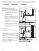
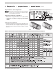
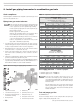
3. Position Electrode first — Make sure the electrode is placed according
tothedimensionsshowninFigure6.Toadjusttheelectrode,loosen
theelectrodeclampscrewandslide/rotateintoposition.
Tighten the electrode clamp screw after positioning. The shim rod
weldedintheclamp’sv-groovealignsthebracketwhentightening.
4. Position Flame rod after setting electrode — Make sure the flame rod
is located as shown in Figure 7. To adjust, loosen the flame rod clamp
screw. Tighten the screw to secure the flame rod in place.
5. Replacethecombustionhead/manifoldintheairtube.
Figure 6 Electrode location
Figure 7 Flame rod location
After electrode is adjusted, use
a1/8”drillbittocheckelectrode
spacing to surface per Figure
6.Alsousethedrillbittomake
sure the electrode is no closer
than 1/8” to any other metal
surface.