
Instruction Manual

Model 301GAS burner — Instruction manual
Carlin part number MN301GAS Rev. 03/14/11
– 7 –
Where appliance instructions differ from this manual, follow the appliance instructions.
1. Prepare site • prepare burner • mount burner (continued)
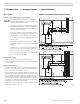
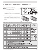
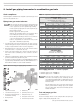
Table 1 Burner orifice sizing, air settings and minimum combustion chamber dimenions (see Figure 3)
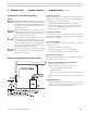
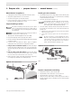
Figure 3 Chamber dimensions & tube configurations
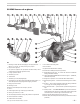
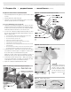
Prepare burner and components
Donotinstalloroperatetheburnerifanycomponentisdamaged
or if burner does not comply with the specifications of Table 1
and other guidelines in this manual.
Combustion head/air tube configurations
• 301GASburnersaresuppliedwitheitheran“B”or“C”headandairtube
combination.The“B”head/tubeisdesignedforthelowrangefrom401
to700MBH.The“C”head/tubeisforthehighrangefrom550MBHto
1,100MBH.
Air tube insertion length (UTL)
• Usableairtubelength(UTL)isthedistancefrommountingangetoend
ofairtube.Verifythattheendoftheairtubewillbeushwith,ornomore
than¼inchshortof,theinsideoftheappliancecombustionchamberfront
wall when the burner is mounted. See Figure 3 and Table 1 for further
information.