
Instruction Manual

Model 301GAS burner — Instruction manual
Carlin part number MN301GAS Rev. 03/14/11
– 3 –
Where appliance instructions differ from this manual, follow the appliance instructions.
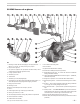
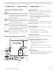
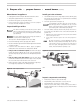
301GAS burner at-a-glance
1 Manual gas valve (wtih two test tappings) –Gas supply entrance — 1”
NPT; 5” w.c. min; 14” w.c. max; natural gas or propane
2 Gas pressure regulator
3 Gas pressure regulator vent port (tted with xed orice; vent to
outside where required by applicable codes)
4 Low gas pressure switch
5 Automatic gas valve
6 Junction box
7 Automatic gas valve (diaphragm type)
8 Diaphragm gas valve bleed port (tted with xed bleed orice) – in-
staller must provide vent piping from this tapping to outside
9 High gas pressure switch
10 Manual gas valve
10a Burner gas manifold pressure test port, 1/4” NPT
11 Union
12 Orice nipple (burner gas orice plug located inside)
13 Burner gas connection, 1” NPT
14 Air tube (ange omitted for clarity), with powder coat paint nish
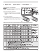
15 Flame rod/insulator assembly
16 Combustion head assembly
17 Gas saddle connection gasket
18 Gas manifold
19 Ignition electrode/insulator assembly
20 Static disk assembly (low input range shown)
21 Hinged burner ange door – for access and removal of combustion
head/gas manifold assembly
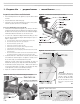
22 Ignitor (Carlin Model 41800 solid state electronic ignitor — 9,000 volts,
continuous duty rated)
23 Hinged cover plate (for access to blower wheel & electrodes)
24 Airow proving switch — Prevents burner from ring if air is not mov-
ing
25 Air band — Only a single adjustment required for setting combustion
air; see page 7 for starting setting based on input
26 Door interlock switch — prevents burner operation if anged door is
open
27 Primary control — Carlin Model 60200FR microprocessor-based inter-
rupted ignition ame supervisory control (ame rectication); Flame
current test jack is located to right of control terminal strip
28 Burner junction box (installer electrical entrance)
29 Motor (with permanently-lubricated bearings and thermal overload
protection)