
Instruction Manual

Model 301GAS burner — Instruction manual
Carlin part number MN301GAS Rev. 03/14/11
– 20 –
Where appliance instructions differ from this manual, follow the appliance instructions.
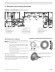
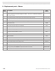
9. Replacement parts – Burner
Item
number
Description Part
number
1 Air tube with gasket and flanged door assembly; welded appliance flange shown (specify
appliance application and overall length of air tube) — “B” and “C” combustion head/tube
assemblies available
Consult factory
2 Gas manifold (specify overall length of air tube and input range required) Consult factory
3 Flanged door nuts (four required) 28357
4 Blower housing (with scroll extension and pressure augmenter) NA
5 Air band (four-slot) 47001S
6 Air shutter, low input range (“B” head/tube)
Air shutter, mid input range (“C” head/tube)
99254
99278
7 Blower wheel, 5¾“ diameter x 4“ deep 28563S
8 Motor, Carlin PSC, 1/6 hp, 3450 RPM 98611S
9 Combustion head assembly, “B” head
Combustion head assembly, “C” head
99164
99277
10 Electrode/flame rod bracket assembly 99153KIT
11 Ignitor electrode 99158
12 Flame rod 99161
13 Airflow switch and mounting plate assembly (sensing lines not shown, but included with kit) 98521KIT
14 Door interlock switch and mounting screws 99261KIT
15 Ignitor, Carlin electronic Model 41800 4180002C
16 Burner junction box, 4" x 4", with grommet, lock washer, conduit nipples (to burner housing) 99198KIT
17 Primary control, Carlin 60200FR microprocessor flame rod control 602002FR943S
18 Optional adjustable forced draft flange 99255