
Instruction Manual

Model 301GAS burner — Instruction manual
Carlin part number MN301GAS Rev. 03/14/11
– 11 –
Where appliance instructions differ from this manual, follow the appliance instructions.
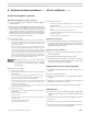
3. Wire burner
General wiring requirements
Read and follow the guidelines below. Failure
to comply could result in severe personal injury,
death or substantial property damage.
Electrical shock hazard—Disconnectelectrical
supply to the burner before attempting to service.
Electrically ground burner — The burner must be
grounded in accordance with local codes or, in the
absence of local codes, with the National Electrical
Code,ANSI/NFPA70,or
CSAC22.1/CSAC22.2
Canadian Electrical Code for Canadian installs.
Label all wires before removing for servicing. Wiring er-
rorscouldresultinunsafeappliance/burneroperation.
Readappliancemanufacturer’sinstructionscom-
pletely before wiring burner.
The60200FRcontrolrequiresaconstant120
vac
power source from the appliance as well as power
from the appliance limit circuit. See Figure 11.
Check polarity carefully. If hot and neutral wires are
reversed at appliance power source, the control will
lockout on flame failure.
If replacing any of the wire supplied with the burner,
use minimum #18 AWG 125°C or better.
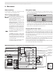
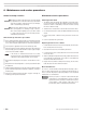
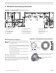
Figure 11 Wiring diagram — 301GAS burner with 60200FR primary control
Verify power supply
1. The burner requires a 120 vac/60hz/single-phasepowersupply,withatleasta10-amp
fuse. The current draw will be (when equipped with typical motor and Carlin 41800
electronic ignitor) approximately:
2. The 120 vac powerconnections tothe blackand red/whitewires of the 60200FR
must be the same polarity from the same power source.DONOTattempttosupply
separatepowersources.Checkthepowerfromtheappliancewithavoltmeter.Verify
thatthesupplytotheblackandred/whitewiresarefromthe120
vac HOT side and
that the power is no less than 102
vac nor more than 132 vac.
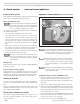
Checking burner flame signal
The60200FRusesamerecticationtodetecttheame.Becausethegroundedmetal
surface area near the flame rod is much larger than the surface of the flame rod, current
flows through the flame more easily in one direction than the other. This causes an AC
voltageappliedtotheamerodtoresultinaDCcurrent.(Notethat,iftheamerodshould
touchagroundedmetalpart,thecurrentwouldbeAC,notDC,andthecontrolwouldnot
sense flame causing a flame failure.)
The60200FRcontrolhasa3mmamesignaltestjack(nexttotheterminalblock)that
canbeusedwithaamesignalmeter,suchastheHoneywellW136.Oryoucanusea
standard 3 mm stereo plug fitted with two leads (Carlin part number 99017). Connect these
leadsinserieswithyourammeterleadstoreadDCmicroamps.
Theminimumamesignalneededtosatisfythe60200FRsensingcircuitis0.8microamps.
The control will register flame failure at any lower signal.
Black
call for heat 120 from limit circuit
VAC
White
Orange
Blue
Red/White
From appliance 120
power source
for constant power
VAC
From appliance 120
limit circuit to
start burner on call
VAC
Connect to
appliance
neutral entrance
120
VAC
Connect ground per
NEC, CEC or local
constant 120 lineVAC
Violet
Violet
Black/White
A
A
Dry contacts to alarm circuit
(24 or , max load 2)
VACDC AMPS
60200FR
Burner junction box
Ignitor
Electrode
Green
Brown
Flame rod
Chassis ground
Airflow
switch
Jumper or 24 to thermostat
(anticipator setting 200 mA)
VAC
T
T
30113-R1
Red
Lo gas pr sw
Black/
Ye llow
Hi gas pr sw
Flg. Door Switch
Black
Ye llow
Ye llow
Black
Black
Yellow
Installer
wiring
Wire
nuts
Crimp
connectors
Black/White
White
White
Motor
Gas train junction box
NO
Com
Com
NC
Black/
Ye llow
Black
Black
Solenoid valve
Diaphragm valve
White
White
White
Ye llow
Black
Black/White
Black/White
Code compliance
Theburner/applianceinstallationmustcomplywithcodeslisted
on page 2 and any other locally applicable codes.