
Instruction Manual

Model 301GAS burner — Instruction manual
Carlin part number MN301GAS Rev. 03/14/11
– 10 –
Where appliance instructions differ from this manual, follow the appliance instructions.
2. Install gas piping from meter to combination gas train
Code compliance
Theburner/applianceinstallationmustcomplywithcodeslistedonpage2and
any other locally applicable codes.
Piping from gas meter to burner
Connect from the gas supply to the burner gas train inlet using
new,cleanblackironpipeandmalleableironttingsonly.Do
not use copper, brass, cast iron or galvanized pipe or fittings.
Providesupportforgaspiping.Donotresttheweightofthegas
piping on burner gas train.
Provide a support for the burner gas train.
Apply pipe dope sparingly at all joints. Use only pipe dope listed
forusewithpropanegas.Donotusepipesealingtape.
Donotholdthegasvalvewithpipewrench.Usecrescentwrench
orothersmooth-jaweddevice.Donotovertighten.
Failure to comply with above could result in severe personal
injury, death or substantial property damage.
1. If possible, install a new gas line directly from the gas meter. If you are
using an existing gas line, verify it is clean and in good condition, and verify
it is large enough to handle the load of all connected appliances.
2. When branching from a common gas line, do not tap off from the bottom
of horizontal sections — only from the side or top.
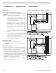
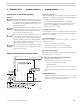
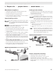
3. Install a main manual shutoff valve, sediment trap and ground joint
union near the burner combination gas valve connection as shown in
Figure 10.
4. If the burner is installed inside an appliance jacket, install the main manual
gas valve and sediment trap external to the jacket.
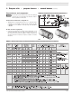
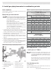
5. Size piping (or verify size) using Table 2. You will find additional information
ongaslinesizingintheNationalFuelGasCode,NFPA54/ANSIZ223.1,or
B149.1/B149.2InstallationCodeforCanadianInstallations.
Gas supply pressure — natural or propane
• Maximumsupplypressure: 14 inches w.c.
• Minimumsupplypressure: 5 inches w.c.
Donotexposethegastraintogaspressureinexcessof14
inches water column. Higher pressure could damage the valve
seat, resulting in potentially hazardous condition. When pressure
testing piping at higher pressures, disconnect burner from gas
line before testing.
If the gas supply pressure can exceed 14 inches water column at
any time, you must install a lockup type gas pressure regulator
in the gas supply piping, ahead of the main manual gas valve
installed at the burner.
Test and purge gas line
Read WARNING above.
Pressure test and purge the line. Pressure testing should be done by the gas
supplier or utility, following all applicable codes.
1 Pipe to meter or branch
2 T-handle main manual gas valve
3 Use clean, burr-free black iron pipe
and malleable iron ttings
4 Ground joint union
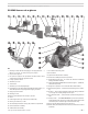
Figure 10 Connecting gas supply piping to burner
Table 2 Capacities of black iron pipe, cubic feet gas/hour
5 Sediment leg
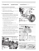
6 Upstream pressure tap, 1/4”
7 Outlet pressure tap, 1/4”
8 Gas regulator access screw
9 Gas valve wire junction box
NATURAL GAS
Capacities in Cubic feet per hour
for Schedule 40 metal pipe
Pipe size
(inches)
Total length of gas piping,
from meter to burner connection (feet)
20 40 60 80 100
Natural gas @ .60 specic gravity, pressure drop 0.3 in. w.c.
(note 1)
1¼ 730 500 400 350 305
1½ 1,100 760 610 530 460
2 2,100 1,450 1,150 990 870
2½ 3,300 2,300 1,850 1,600 1,400
Natural gas @ .60 specic gravity, pressure drop 0.5 in. w.c.
(note 1)
1 465 320 260 220 195
1¼ 950 660 530 460 400
1½ 1,460 990 810 690 620
2 2,750 1,900 1,520 1,300 1,150
2½ 4,350 3,000 2,400 2,050 1,850
Note 1
For natural gas with specic gravity other than 0.60, consult
National Fuel Gas Code, NFPA 54/ANSI Z223.1, or Canadian
B149.1/B149.2 for correction factor.
PROPANE GAS
Capacities in Btuh for
Schedule 40 metal pipe
Propane gas @ 1.5 specic gravity, pressure drop 1 psi
½ 1,684 1,157 929 795 705
¾ 3,521 2,420 1,943 1,663 1,474
1 6,632 4.558 3,660 3,133 2,776
Propane gas @ 1.5 specic gravity, pressure drop 0.5 in. w.c.
1 735 506 411 348 308
1¼ 1502 1043 838 727 632
1½ 2308 1565 1281 1091 980