
Install Instructions

Start-up & Operation
Do not start the burner if the combustion chamber
contains oil or oil vapor.
Per UL requirements, the control will not turn on if the
CAD cell senses ame during the self-test. If the CAD cell sees light (ame) at the beginning of a cycle, the control will remain in
self-test mode until the CAD cell no longer senses light (flame). The amber LED will blink momentarily
every 3 to 4 seconds and
green LED will be on or flashing
.
Power ON Open all manual oil line valves. Close the line switch.
Self-test 1 The control performs a “boot-up” test to verify internal operation each time power is applied to the black
wire. The amber LED turns on and the test continues for about 5 seconds. If the test fails, the control turns
the amber LED off and repeats this test sequence until successful.
Stand-by (No call for heat) If Self-test 1 is successful, amber LED turns off and control waits for heat call.
Call for heat Set thermostat and limit to call for heat. Thermostat circuit must be closed and power coming to black
wire from limit circuit.
Self-test 2 If a failure occurs in this self-check, the control won’t start and the amber LED blinks 1 second on, 4 sec-
onds off, until serviced or the problem clears. These failures include CAD cell seeing light, internal fault, or
line voltage <90V. See service section.
Burner on After the self-test, amber LED turns off. The ignitor starts, followed 2 seconds later by the motor.
Pump Prime To enter pump prime: 1. Start a CFH cycle. During Pre-Ignition, press Reset. Motor turns off (10 seconds),
then release the button. When motor turns back on, within 5 seconds, press the Reset button until the
amber LED starts to ash. You are in Pump Prime, release Reset button.
Optional Pump Prime notes: 1) If lost, press Reset for 1 second and release, then if the control is not in
Pump Prime, restart the sequence. 2) If Reset is released before end of rst 10 seconds, the control re-
turns to Standby and restarts another CFH cycle. 3) If reset is not pressed the second time, a normal CFH
cycle will continue. 4) If motor and ignitor are on and amber LED is ashing, the control is in Pump Prime.
5) Pump Prime will exit standby if ame is detected, or 60 seconds has elapsed, or loss of TT or Limit, or
Reset button is pressed.
TFI The CAD cell must sense ame within the TFI time limit (trial for ignition). Insufcient ame puts control into
lockout.
Run The burner continues firing during call for heat if the CAD cell is sensing flame. Only the green LED is on during
normal running.
Lockout If CAD cell does not sense ame within the TFI time limit after the burner starts, lockout occurs. The con-
trol turns the red LED on constant, and closes the alarm contact.
To Reset Push in and hold reset button for 2 seconds, then release.
Latch-up If the control locks out 3 times during a single call for heat, latch-up occurs. The control turns on both the
amber and red LEDs constant. You must use the special procedure below to reset the control after latch-up.
Reset after latch-up: Only a qualified service technician should attempt to reset the control after latchup.
The problem that caused the repeated burner lockouts must be corrected before returning the burner to
normal operation.
To Reset
Push in and hold the reset button for 10 seconds. The amber LED will begin to ash.
After the LED begins flashing, continue holding the reset button for 20 seconds. The LEDs will turn off. Re-
lease the reset button and the control will restart (releasing the button before the LEDs turn off will cause the
control to remain in latch-up)
.
The 40200 & 42230 controls will retain lockout or latchup if power is interrpted.
Flame
If the CAD cell loses ame signal during operation (after the TFI), the red LED ashes. Recycle: Control
Failure
waits for 65 seconds (with red LED flashing), then begins again at Self-test 2. Red LED goes off .
If the green LED is blinking during a run, the ame is weak or unstable which may cause recycle.
Stand-by
Control remains in stand-by mode until limit circuit sends power to the black wire and thermostat circuit
closes (call for heat).
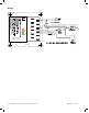
Model 40200 & 42230 Diagnostic LEDs
– Amber OFF – Amber ON – Amber FLASHING
– Green OFF – Green ON – Green FLASHING
– Red OFF – Red ON – Red FLASHING
© Copyright 2014 - Carlin Combustion Technology, Inc. MN40200E 111214