CARL GOLDBERG PRODUCTS LTD. P.O. Box 818, Oakwood, GA 30566 • 678-450-0085 • Fax: 770-532-2163 • www.carlgoldbergproducts.com ©copyright 2003 Carl Goldberg Products, Ltd.
WARNING! THIS IS NOT A TOY! THIS IS NOT A BEGINNERS AIRPLANE This R/C kit and the model you will build from it is not a toy! It is capable of serious bodily harm and property damage. It is your responsibility, and yours alone - to build this kit correctly, properly install all R/C components and flying gear (engine, tank, radio, pushrods, etc.
Ex-tr eme 5 40 Congratulations on your purchase of the Lanier Ex-treme 540 3-D ARF. This is a very unique aircraft, with great 3-D capabilities. Every effort has been made to produce a lightweight, straight, easy to assemble aircraft. Because of its oversize control surfaces which are double beveled to allow for extreme throws, great care must be taken in the set-up and flying of this airplane.
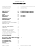
Parts Layout 4
Hardware List 2.5mmx10mm screws 2.
BUILDING INSTRUCTIONS D C Before starting to build this kit, we urge you to read through these instructions. They contain some important building sequences as well as instructions and warnings concerning the assembly and use of the model. We expect that you have some building experience to take on this model. However, every minute detail is not covered. This is not a basic trainer. The instructions together with the simplicity of this kit will allow you to produce a first class EX-TREME 330 3D.
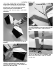
It is easier to do some of the work on the wing and fuselage before you glue them together. Locate the template at the rear of the book for locating the landing gear and cut it out with scissors. Place it over the fuselage and drill 1/8” holes at the location of the mounting holes. Check the aluminum gear and make sure it matches the holes in the paper, if not transfer those holes and use the template to get the right angle. Mount with the output arm forward.
measure back from the opening 13/8” and cut a slot 1/8” wide centered on the mark you made. we are now ready to mount the wing on the fuselage. Slide the wing back in the fuse, almost to the wing joint. Coat the bare balsa at the joint with 30 minute z poxy and slide the wing in the rest of the way. Use your marks to realign the wing, then remeasure A to B, and C to D. Clean up any zpoxy that squeezed out with a paper towel and alcohol. Block the entire assembly on your workbench until cured.
width of stab Locate the elevator joiner wire and the two elevator halves. Measure the width of the stab and lay the elevators spread to that length. Mark the location of the holes for the elevator joiner wire on the stab. Install the gear on the fuselage using the two 3mmx30mm bolts, four 3mm flat washer, and two 3mm lock nuts. Drill a 1/8” hole at the location of the mark and notch the leading edge of the stab so the wire will be flush with the leading edge. Repeat for the other elevator half.
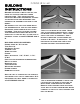
Glue the joiner wire in place with epoxy. Make sure the elevators are lying on a flat surface so both will be parallel. Use a straight edge to make sure the leading edge is straight and the tips are at the proper width. elevator wire Fit the rudder in place on the fin and mark the location of the elevator wire. Fit the elevators in place on the CA hinges. tail wheel tiller arm Go to the bottom of the rudder and mark the location of the tail wheel tiller arm.
notch for elevator wire hole for tail wheel wire Deflect the rudder fully in one direction and glue the CA hinges with two drops of thin CA each. Deflect in the other direction and glue the hinges on the other side. When the epoxy has cured you can remove the masking tape. At the location of the elevator wire make a notch approximately 3/16” deep and 3/8” wide to clear the elevator wire.
Locate one of the 2mm pushrods with clevis. install the silicone keeper over the clevis and attach to the control horn. With the aileron centered and the aileron servo centered, mark the location of the bend over the output hole in the servo arm. Bend at 90 degrees and cut off at 3/8”. The servo arm will need to be drilled with the 5/64” drill. Install the pushrod through the servo arm and retain with a nylon snap-r-keeper. Repeat for the other aileron.
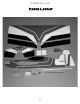
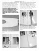
The battery will mount on the left side. Wrap with foam rubber(not shown for clarity) and insert into opening. Using a sharp knife or razor blade, remove the covering from the servo cutout just ahead of the stab on both sides of the fuselage. exit hole for antenna The receiver will mount on the right side in the opening next to the servo. Wrap with foam rubber(not shown). Route the antenna under the pushrod and exit from a hole close to the side of the fuselage.
It will be necessary to cut the back side out of the nylon cover for the wires to fit in. Using a sharp knife, cut 1/16” inside the edge of the cover. Make sure you are cutting the back side, it fits on the right side of the plane. The wires can then be fitted inside by staggering the plugs. location of hole in wing You will need a 12” servo extension for both rudder and elevator servos. Fit the wires into the cover, and leads into the opening in the wing.
Align the elevator horn on the inside edge of the elevator and mount using the two #2x1” screws and nylon plate. Locate the two 2mm pushrods with clevis and install the silicone keeper on clevis. Hook clevis to horn and mark where it meets the servo arm. Make a 90 degree bend and cut at 3/8”. You will need to drill out the servo arm with your 5/64” drill and install the rod using the nylon snapr-keeper to retain it. Do this to both rudder and elevator.
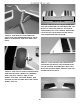
. If you use a mini servo these will not be used. If you use a standard servo you will need them to clear the servo. Install stopper in tank and tighten the bolt in the center until stopper is snug. Don’t over tighten. Clunk should move freely and vent tube should be to the top of the tank. Assemble the tank cap with the big washer, the rubber stopper, and the little washer in the rear. For a two line system we will only use the long piece of aluminum tube and one short one.
Mount the throttle servo using the hardware supplied with the radio. Use the1.5 mm x 6”pushrod and bend a z bend in one end and attach to the throttle arm on motor. Attach the ez connector to a three hole servo arm and attach to servo. Locate the two hatch access doors. Drill a 3/32” hole in all four corners of each hatch. Space the holes off each side 3/32”.
The CG should be between 4-3/4” and 5-1/4” for first flight. For 3-D it can be moved back after you are comfortable with the plane. Have fun! Additional Equipment needed to complete your Ex-T Treme 540 3-D D Minimum of 4 channel radio set required. (4) standard servos (1) mini servo 70oz. servos recommended for high horsepower engines. (3) 12” servo extensions Dubro #222 Medium fuel tubing Dubro #514 1/2” foam rubber 2-1/4 to 2-1/2” spinner .32 - .46 two stroke engine or .40 to .
Exit hole location to be marked on the wing 19
Optional Landing Gear Available Makeyour your Edge Different from crowd! Make Extreme 330 different fromthe the crowed! Our 257Profile ProfileNylon landing gear willGear fit your 540 and looklook great too.too. This Our New new ##257 Landing will Extreme fit you Extreme 300 and great This landing gear also includes our New #302 5/32” x 1-1/2” Polished Nickel Landing Gear Landing gear also includes our new # 302 5/32 x 1-1/2” Polished Nickel Landing Gear Axle you extra value. give you extra value.
Ex-treme 540 EX-TREME 330 3-D ARF The Harrier This maneuver has your plane in very slow forward flight in a nose high 45 degree attitude. To perform it, enter the same way as you would an elevator, then feed in power until the plane maintains altitude and starts to fly forward at a nose high attitude. Maintain it by holding up elevator and adjusting power, use the rudder to change direction. Using ailerons may cause the plane to snap and should be avoided. Add power and push the nose back over to recover.
Ex-treme EX-TREME 330 3-D540 ARF The Waterfall This maneuver has your plane flipping around the axis of the wing, while dropping. Starting from a high altitude, go to low throttle and gradually pull the nose up to near vertical. Just when the plane is about the stall, give it full down elevator and full power. Make attitude corrections with the rudder and ailerons to keep the plane flipping on axis.