Digital Counting Scale CS Series Operation Manual 8526-M256-01 Rev B 07/10 Cardinal Scale Manufacturing Co. PO BOX 151 WEBB CITY, MO 64870 PH (417) 673-4631 - FAX (417) 673-5001 www.detectoscale.com 8526-M256-O1 Rev B • CS Series Technical Support: Ph: 866-254-8261 techsupport@cardet.
8526-M256-O1 Rev B • CS Series
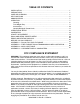
TABLE OF CONTENTS INSTALLATION . . . . . . . . . . . . . . . . . . . . . . . . . . . . . . . . . . . . . . . . . . . . . . . . . PRECAUTIONS . . . . . . . . . . . . . . . . . . . . . . . . . . . . . . . . . . . . . . . . . . . . . . . . CARE AND CLEANING . . . . . . . . . . . . . . . . . . . . . . . . . . . . . . . . . . . . . . . . . . . KEY FUNCTIONS . . . . . . . . . . . . . . . . . . . . . . . . . . . . . . . . . . . . . . . . . . . . . . . ANNUNCIATORS . . . . . . . . . . . . . . . . . . . . . . . . .
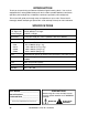
INTRODUCTION Thank you for purchasing our Detecto CS Series Digital Counting Scale. Your scale is equipped with a rechargeable battery pack that is able to provide 100 hours continuous operation (with backlight on) or 200 hours continuous operation (with backlight off). This manual will guide you through setup and operation of your scale. Please read it thoroughly before attempting to operate this scale and keep it handy for future reference. SPECIFICATIONS Displays: (.
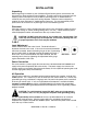
INSTALLATION Unpacking Before beginning installation of your CS Series Digital Counting Scale, make certain the instrument has been received in good condition. Carefully remove the instrument from the shipping carton and inspect it for any evidence of damage (such as exterior dents or scratches) that may have taken place during shipment. Keep the carton and packing material for return shipment if it should become necessary.
PRECAUTIONS Most scales are designed for an office type environment. The CS Series Digital Counting Scale is no exception to that rule. The following should be used as a guideline for the proper environment to operate your scale: • The environment should be free of excessive dust and moisture. • Provide a comfortable temperature. In general, the scale will perform well over a temperature range of 32 to 104° F (0 to +40° C).
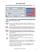
KEY FUNCTIONS This section describes the use of each of the keys on the Digital Counting Scale. It will be helpful to refer to the scale keyboard or the figure below when reading this section. The membrane keyboard is not to be operated with pointed objects (pencils, pens, fingernails, etc). Damage to keyboard resulting from this practice will NOT be covered under warranty. SAMPLE This key is used to weigh a known number of pieces in preparation for a new counting operation.
KEY FUNCTIONS, CONT. M+ Pressing the M+ key will cause the scale to display the contents of the accumulator (the number of pieces accumulated since the last time the accumulator was cleared). The M+ key is also used to add the current piece count value to the accumulator. The M+ annunciator will be selected to indicate the accumulation has taken place.
ANNUNCIATORS The annunciators are turned on to indicate that the scale is in the mode corresponding to the annunciator label or that the status indicated by the label is active. The following describes the functions of each annunciator. Æ0Å (Center-of-Zero) The Center-of-Zero annunciator is located to the left of the WEIGHT display and is selected to indicate that the weight is within +/- 1/4 division of the center of zero.
ANNUNCIATORS, CONT. (Low Battery) The Low Battery annunciator will turn on to indicate that the internal battery requires charging. No change in operation will occur until just before the battery voltage drops to a level where operation is affected. At this level, the scale will automatically turn itself off. NOTE! When the battery needs to be recharged, the CHARGING LED will turn Red. After the battery has been recharged, the CHARGING LED will turn Green.
OPERATION Power Switch The Power Switch is located on the bottom left side panel towards the front of the scale. Place the power switch in the on position. The scale will perform a brief lamp test. This test consists of illuminating all display segments and annunciator LED’s to allow the operator to make a visual verification that the display is operational.
OPERATION, CONT. Counting Weight of Sample is Unknown 1. With the scale in the Weight mode, place the sample on the scale platform. 2. On the numeric keypad, enter the number of pieces in the sample. 3. While the display is blinking, press the SAMPLE SIZE key. 4. Add the pieces to be counted and read the total count on the COUNT display. 5. Remove the pieces from the scale. 6. Press the CE key to complete the counting operation and return to the Weight mode. Sample Weight is Known 1.
OPERATION, CONT. Tare Weight Entry Push Button Tare 1. With the scale in the Weight mode, place the empty container on the scale platform. 2. Press the TARE key. The WEIGHT display will change to zero and the NET annunciator illuminates, indicating net weight is being displayed. The empty container’s weight has been entered as "tare weight". Pre-set Tare with Known Weight of Container 1. With the scale in the Weight mode, press the TARE key. The display will flash $9 ; . 2.
OPERATION, CONT. Accumulator Adding to the Weight Accumulator 1. With the scale in the Weight mode, place the item on the scale platform. 2. Press the M+ key to add to the value of the Weight Accumulator. 3. The PIECE WEIGHT display will flash 33, then change to show the accumulator values (to indicate the addition to the accumulator has taken place). After 3 seconds, the scale will return to the weight mode. 4. Remove the item from the scale. 5.
OPERATION, CONT. Quantity Preset Hi Limit The scale can store a Quantity Preset Hi Limit value. The scale will beep and the unit weight window will display a blinking @0&(@ if the quantity is over the Hi limit value set. 1. Press the COUNT PRESET key (items can be on scale or platform can be empty). 2. The WEIGHT display will change to show dashes (@@@@@). 3. Using the numeric keypad, enter the Quantity Preset Hi Limit. 4. Press the SAMPLE SIZE key, followed by the COUNT PRESET key. 5.
OPERATIONAL SETUP During the Operational Setup, it is necessary to enter values using the scales alphanumeric keypad. In addition, the following keys are also used: KEY • (decimal) CE TARE MC FUNCTION Exit without saving setting Move the cursor left (backward) Move the cursor right (forward) Enter (exit and save setting) Enter Operational Setup 1. With the scale in the Weight mode (0 will be displayed for WEIGHT and will be displayed for the PIECE WEIGHT and COUNT displays), press the ZERO key. 2.
OPERATIONAL SETUP, CONT. 0 ` – Automatic Power-Off 1. With the WEIGHT display showing 0 ` with the 1 flashing, press the 2 key on the alphanumeric keypad. 2. The WEIGHT display will change to 0 ` with the 2 flashing. 3. Press the MC key. 4. The PIECE WEIGHT display will change to show the current setting. 5. If the setting displayed is acceptable, press the MC key to save it. 6.
OPERATIONAL SETUP, CONT. 0 ` – A/D Sampling Speed 1. With the WEIGHT display showing 0 ` with the 4 flashing, press the 5 key on the alphanumeric keypad. 2. The WEIGHT display will change to 0 ` with the 5 flashing. 3. Press the MC key. 4. The PIECE WEIGHT display will change to show the current setting. 5. If the setting displayed is acceptable, press the MC key to save it. 6. Otherwise, select the desired setting for the A/D Sampling Speed and press the MC key to save it.
OPERATIONAL SETUP, CONT. 0 ` – Zero Tracking Range 1. With the WEIGHT display showing 0 ` with the 6 flashing, press the 7 key on the alphanumeric keypad. 2. The WEIGHT display will change to 0 ` with the 7 flashing. 3. Press the MC key. 4. The PIECE WEIGHT display will change to show the current setting. 5. If the setting displayed is acceptable, press the MC key to save it. 6. Otherwise, select the desired setting for the Zero Tracking Range and press the MC key to save it.
OPERATIONAL SETUP, CONT. 0 ` – Pre-Tare Mode 1. With the WEIGHT display showing 0 ` with the 8 flashing, press the 9 key on the alphanumeric keypad. 2. The WEIGHT display will change to 0 ` with the 9 flashing. 3. Press the MC key. 4. The PIECE WEIGHT display will change to show the current setting. 5. If the setting displayed is acceptable, press the MC key to save it. 6. Otherwise, select the desired setting for the Pre-Tare Mode and press the MC key to save it.
OPERATIONAL SETUP, CONT. 0 ` – Accumulation Acceptable Condition 1 1. With the WEIGHT display showing 0 ` with the 0 flashing, press the 1 key on the alphanumeric keypad. 2. The WEIGHT display will change to 0 ` with the right 1 flashing. 3. Press the MC key. 4. The PIECE WEIGHT display will change to show the current setting. 5. If the setting displayed is acceptable, press the MC key to save it. 6.
CALIBRATION During the Calibration process, it is necessary to enter values using the scales alphanumeric keypad. In addition, the following keys are also used: KEY • (decimal) CE TARE MC FUNCTION Exit without saving setting Move the cursor left (backward) Move the cursor right (forward) Enter (exit and save setting) Enter Calibration 1. With the scale in the Weight mode (0 will be displayed for WEIGHT and will be displayed for the PIECE WEIGHT and COUNT displays), press the ZERO key. 2.
GRAVITY ADJUSTMENT IMPORTANT! This scale is equipped with a Gravity Adjustment function which allows the scale to be calibrated in one location and then adjusted to match the gravity at the location where it will be used. During the Gravity Adjustment process, it is necessary to enter values using the scales alphanumeric keypad.
RS232 AND SERIAL PRINTER SETUP During the RS232 and Serial Printer Setup, it is necessary to enter values using the scales alphanumeric keypad. In addition, the following keys are also used: KEY • (decimal) CE TARE MC FUNCTION Exit without saving setting Move the cursor left (backward) Move the cursor right (forward) Enter (exit and save setting) Enter RS232 and Serial Printer Setup 1.
RS232 AND SERIAL PRINTER SETUP, CONT. 9: ` – Communication Protocol Setting 1. 2. 3. 4. 5. 6. With the WEIGHT display showing 9: ` (with the 1 flashing), use the alphanumeric keypad to enter 0 and 2. The WEIGHT display will change to 9: ` with the 2 flashing. Press the MC key. The PIECE WEIGHT display will change to show the current setting. If the setting displayed is acceptable, press the MC key to save it.
RS232 AND SERIAL PRINTER SETUP, CONT.
RS232 AND SERIAL PRINTER SETUP, CONT. 9: ` – Output Counts Setting per Second in Continuous Transmission 1. 2. 3. 4. 5. 6. With the WEIGHT display showing 9: ` (with the 3 flashing), use the alphanumeric keypad to enter 0 and 4. The WEIGHT display will change to 9: ` with the 4 flashing. Press the MC key. The PIECE WEIGHT display will change to show the current setting. If the setting displayed is acceptable, press the MC key to save it.
RS232 AND SERIAL PRINTER SETUP, CONT. 9: ` – Operation Mode Setting 1. 2. 3. 4. 5. 6. With the WEIGHT display showing 9: ` (with the 4 flashing), use the alphanumeric keypad to enter 0 and 5. The WEIGHT display will change to 9: ` with the 5 flashing. Press the MC key. The PIECE WEIGHT display will change to show the current setting. If the setting displayed is acceptable, press the MC key to save it.
RS232 AND SERIAL PRINTER SETUP, CONT. 9: ` – Zero Reset Condition for Automatic Transmission Setting 1. 2. 3. 4. 5. 6. With the WEIGHT display showing 9: ` (with the 6 flashing), use the alphanumeric keypad to enter 0 and 7. The WEIGHT display will change to 9: ` with the 7 flashing. Press the MC key. The PIECE WEIGHT display will change to show the current setting. If the setting displayed is acceptable, press the MC key to save it.
ERROR AND STATUS DISPLAYS The Digital Counting Scale is equipped with a diagnostic software program that tests various portions of the instrument’s circuitry and verifies proper operation. Should a problem be detected, an error or status message will be displayed alerting the operator to that condition.
APPENDIX 1 – RS-232 FULL DUPLEX FORMAT 8526-M256-O1 Rev B • CS Series 27
APPENDIX 1 – RS-232 FULL DUPLEX FORMAT, CONT.
APPENDIX 2 – FIXED FORMAT RS-232 TRANSMISSION LINE ILLUSTRATION 8526-M256-O1 Rev B • CS Series 29
APPENDIX 3 – ASCII CODE TABLE 30 8526-M256-O1 Rev B • CS Series
APPENDIX 4 – 7-SEGMENT DISPLAY CHARACTERS 8526-M256-O1 Rev B • CS Series 31
32 8526-M256-O1 Rev B • CS Series