
Installation Guide

_________________________________________________________________________________________________________________________
Card Access
™
InHome
™
Heavy-Duty Power Controller Installation Guide / Wiring Diagram Page 8 of 12
Card Access, Inc.
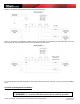
1 Button: Toggle Relay A, Momentary Relay B. This gives the user the option of having 1 relay
controlled by a toggle switch and the other relay controlled by a momentary pushbutton switch
o The reason that it is labeled Normal Mode is to indicate the individual nature of the relay operation. The
user can do whatever they want with the switch inputs and the relays will follow according to the Type of
switch connected to the input. No relay protection, relay timing or any other specialized relay operation is
added
• Linked Mode (Motor Control)
o This mode is used for controlling motors that do not have built in motor controllers. Many motors
assemblies already have a built in motor controller that governs operation. If your motor assembly has a
built in motor controller we recommend using Normal mode to control your motor assembly. If your
application does not have a built in motor controller you can use this mode to control your motor. In
linked mode the two relays operate such that both relays cannot be activated at the same time. This
protects the motor assembly from being energized to operate in opposing directions. The relays are also
governed by a “motor travel time” values which allows the motor to be turned off, after initial activation, in
a preset amount of time. Typical applications for Linked Mode – Motor Control use are: Gate open/close
control, Screen up/down control, Blinds open/closed control, or other applications that require two motor
direction operations without a built in motor controller.
1 button, Toggle mode. This mode links the two relays together not allowing one relay to close
while the other is closed and visa versa. (both relays cannot be closed at the same time) A
single button can control the direction of a motor. Press once and relay A closes – (screen
comes down until the motor travel time is reached). Press again and both relays open – (screen
stops). Press again and relay B closes – (screen goes up until motor travel time is reached).
Press again and screen stops. Press again and the cycle repeats.
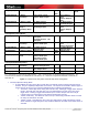
2 button momentary – as described in the table
3 button latched – as described in the table
Delay Learning Mode. This mode allows you to set or change the Maximum Motor Travel time
limit. The Default time limit is set to 15 seconds. A new time limit can be stored by the user, and
once stored, is then used in all future Linked (Motor Control) Mode operations. The user sets this
time by pressing and holding the Input 1 Switch for the desired time delay. This is accomplished
as follows: Upon pressing Input 1, Relay “A” closes and the LED will turn yellow and will begin
blinking at a 1 second rate (screen is going down). When the Input 1 button is released, Relay
“A” opens and the LED turns to red (screen stops) and the delay time is temporarily saved. The
time is then permanently stored in the device by pressing and holding the ID button for 4
seconds. Holding the ID button for 4 seconds will cause the LED to flash yellow 3 times
indicating that a new default time value has been permanently stored in the device. The
Maximum Motor Travel time is limited to 255 seconds. The user can now switch to any other
Linked (Motor Control) Mode dip switch setting and the newly saved time will be applied to all
relay operations. The user can disable the Maximum Motor Travel time limit (setting value to
zero) by pressing and holding the ID button without previously activating any relay (not pressing
and holding Input Switch 1). Pressing and holding the ID button for 4 seconds two times in a row
will set the Maximum Motor Travel time limit to zero and disable all timed operations.
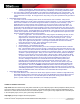
• Linked (Simulated SPDT) Mode
o This mode allows the user to link the two SPST relays together in order to simulate a single SPDT relay.
Essentially what this means is that when relay A is open relay B will always be shut and when relay B is
open relay A will always be shut. This mode will operate in SPDT mode as long as the device has
power. If power is lost the relays will default to the normally open position.
Software Installation Instructions
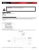
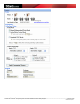
Step Seven Add the InHome Heavy-Duty Power Controller to your Composer project. When prompted to identify the unit,
press the ID button, located on the PC board, four times. The InHome Wireless Contact Relay LED will blink the green
LED twice to confirm the ID has been sent to the Control4 system. To set up the 2 relay outputs and the 4 contact inputs
in the Composer project, refer to your system setup documentation.
Step Eight (Optional) Configure advanced properties.