
Installation Guide

_________________________________________________________________________________________________________________________
Card Access
™
InHome
™
Heavy-Duty Power Controller Installation Guide / Wiring Diagram Page 7 of 12
Card Access, Inc.
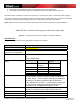
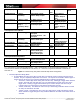
OFF|OFF|OFF|ON 2 Button, Latched Relay A Close Relay
A
Open
Relay B Close Relay B
Open
ON|OFF|OFF|ON 1 Button,
Momentary
Press: Relay A Close
Release: Relay A Open
Press: Relay B
Close
Release: Relay B
Open
OFF|ON|OFF|ON 1 Button, Toggle 1st: Relay A Close
2nd: Relay A Open
1st: Relay B Close
2nd: Relay B Open
ON|ON|OFF|ON 1 Button: Toggle
Relay A
Momentary Relay
B
1st: Relay A Close
2nd: Relay A Open
Press: Relay B
Close
Release: Relay B
Open
Linked (Motor Control) Modes
OFF|OFF|ON|OFF 1 Button, Toggle 1st: Relay A Close. 2nd:
Both Open
3rd: Relay B Close. 4th:
Both Open
ON|OFF|ON|OFF 2 Button,
Momentary
Press: Relay A Close
Release: Both Open
Press: Relay B
Close
Release: Both Open
OFF|ON|ON|OFF 2 Button, Toggle 1st: Relay A Close
2nd: Both Open
1st: Relay B Close
2nd: Both Open
ON|ON|ON|OFF 3 Button, Latched Relay A Close Both
Open
Relay B Close
OFF|OFF|ON|ON Delay Learning
Mode
1st: Relay A Close.
Release: Both Open
2nd: Relay B Close.
Release: Both Open
Linked (Simulated SPDT) Modes
ON|OFF|OFF|OFF 1 Button,
Momentary
Press: Relay A Close
Release: Relay B Close
OFF|ON|OFF|OFF 1 Button, Toggle 1st: Relay A Close
2nd: Relay B Close
ON|ON|OFF|OFF 2 Button, Latched Relay A Close Relay B Close
1st = “First Press” or “First Contact Input Closure,” 2nd = “Second Press” or “Second Contact Input Closure,” etc.
Card Access and InHome are trademarks of Card Access, Inc. Control4 is a registered trademark of Control4, Inc.
STK-HPC-10
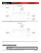
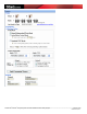
Figure 2 – InHome Heavy-Duty Power Controller Dip Switch Configuration
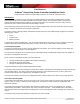
• Normal (Independent Relay) Mode:
o In Normal Mode the relays do just what you tell them to do without regard to anything else that may be
involved. They act completely independent of each other. The 4 inputs can be wired to different types of
closure devices and are set up to control the individual relays in following configurations:
Two button, Latched (Dip switch setting OFF OFF OFF ON) Hooking up a toggle switch between
inputs 1 and 2 will open and close relay A as you switch between one side or the other of the
toggle switch. Hooking a toggle switch between inputs 3 and 4 will open and close relay B.
Latched refers to the switch stays in that position until moved by the user.
1 Button, Momentary. This allows the user to wire up a momentary pushbutton switch to control
the relays as described in the table
1 Button, Toggle. This allows the user to wire up a single switch, usually a momentary contact
switch and then to toggle through the relay conditions defined in the table
as the switch closure is
activated.