
Installation Guide

_________________________________________________________________________________________________________________________
Card Access
™
InHome
™
Heavy-Duty Power Controller Installation Guide / Wiring Diagram Page 6 of 12
Card Access, Inc.
into the fixed wiring. Device must be wired by an authorized
electrician in accordance with the National Electrical Code,
ANSI/NFPA 70-1987. In the European community, the unit must be
wired by an authorized electrician in accordance with all applicable
European codes.
Step One Choose an appropriate location to place the InHome Heavy-Duty Power Controller which ensures the following:
• Device will be appropriately protected from environmental conditions
• Device can be screw mounted to a stable surface
• Location provides easy access to any externally connected wires
• Location ensures a good wireless connection into your ZigBee mesh network if using with a Control4 system.
•
NOTE: Make sure the InHome Heavy-Duty Power Controller is positioned for good ZigBee
wireless reception by (1) ensuring it is within 150 feet of another ZigBee device and (2) avoiding
other electrical equipment that may cause interference with the ZigBee signal (such as cordless
telephones that operate on the 2.4 GHz frequency).
NOTE: We recommend you not place the InHome Heavy-Duty Power Controller ?????.
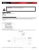
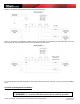
Step Two Thread the low voltage (Class B) external contact input control wires, and the low voltage power supply wires
through the wall of the enclosure which is opposite and on the same end as the Antenna connector. These wires can be
secured to the enclosure using conduit or feed through clamps. Secure the wiring to the terminal strip as illustrated in the
Low Voltage wiring diagram
Step Three Thread the High Voltage wires through the wall of the enclosure on either side of the high voltage terminal
end of the device. These wires can be secured to the enclosure using conduit or feed through clamps. Secure the wiring
to the terminal strip using an appropriate option as illustrated in the High Voltage wiring
Step Four Insert and tighten the mounting screws.
Step Five
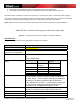
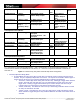
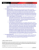
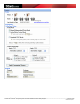
Step Six Select the desired operational mode by setting the dip switches located on the PCB to the appropriate position.
The operational modes are described below:
Figure 2 below shows describes the dip switch settings available to configure the electrical characteristics of InHome
Heavy-Duty Power Controller when controlling specific types of target devices.
Dip Switches
1 | 2 | 3| 4
Type Input 1 Input
2
Input 3 Input 4
Default Settings
OFF|OFF|OFF|OFF Control4 Mode Configured through Control4® Automation System
Normal (Independent Relay) Modes