
Installation Guide

_________________________________________________________________________________________________________________________
Card Access
™
InHome
™
Heavy-Duty Power Controller Installation Guide / Wiring Diagram Page 3 of 12
Card Access, Inc.
1. Connecting a 100-240VAC line power to the High Voltage terminals of the device
2. Connecting a 12VDC power supply to the power inputs of the Low Voltage terminal connector
No power jumpers or setting are required just connect one or the other (line power or external DC power supply in).
The device is designed to be permanently mounted in a fixed location. Power cables can be connected to the device
using conduit or by connecting flexible power lines to the device with feed through cable clamps.
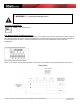
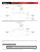
Figure 1 below shows you where the InHome Heavy-Duty Power Controller is placed in a typical installation.
GRAPHIC TBD – show fixed mounting by conduit and by cable clamp
Figure 1 – InHome Heavy-Duty Power Controller in a Typical Installation
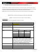
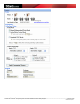
Specifications
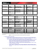
Specifications for the InHome Heavy-Duty Power Controller are as follows:
HPC10A Specifications
Dimensions 4.6” x 10.5” x 2.1”
Weight 3.5 Lbs
Maximum Ambient
Operational Temperature
75 C
Power Input 100-240VAC at 50/60Hz, 0.1 Amps
Or
12VDC, 200mAmps
Relay Contact Ratings (per
relay)
Voltage Load Type Contact
Rating
240VAC General
Purpose
30 Amps
240VAC UL Resistive 25 Amps
120VAC Motor 1 HP
240VAC Motor 2 HP
277VAC Ballast 10 Amps
HV wiring 8 – 14 Gauge wiring depending on Load*
* An accessible disconnect device shall be installed into
the fixed wiring. Device must be wired by an authorized
electrician in accordance with the National Electrical
Code, ANSI/NFPA 70-1987. In the European community,
the unit must be wired by an authorized electrician in
accordance with all applicable European codes
Operational Environment Device shall be mounted in a dry moisture protected
location in accordance with National Electrical Code