
Assembly Instructions


16/01/2019 Shapeoko Assembly Guide - Carbide 3D
https://docs.carbide3d.com/assembly/shapeoko/s3/ 15/35
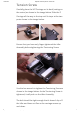
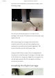
Adjust the eccentric nuts for all 3 of the plates (6
eccentrics total). The Z-axis eccentric nuts should not
need to be adjusted.
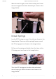
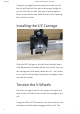
Installing the Left Y-Carriage
In this step, you will be installing the extrusion with
the threaded mounting holes on the back side!
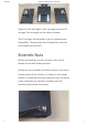
The bag labeled ‘extrusions’ contains 24 pieces of
M6x12mm button head cap screws. These screws are
used to attach the carriages, and the base frame to the
extrusions. These screws require the 4mm hex key.
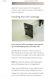
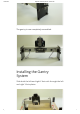
NOTE: the V-rail on the extrusion should be facing the
front, with the stepper motor on the opposite side.
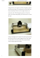
Using 4 pieces of M6x12mm screws, attach the left Y-
Axis plate to the X-axis rail by installing the screws
through the 4 open holes on the assembly. Be careful
not to cross-thread the screws as you install them.