6/01/2019 Shapeoko Assembly Guide - Carbide 3D Carbide 3D ☰ Shapeoko Assembly Guide https://docs.carbide3d.
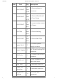
16/01/2019 Shapeoko Assembly Guide - Carbide 3D Packing List Item Part Y-Carriage (LEFT) Y-Carriage (RIGHT) X and Z Assembly Qty Description 1 1 1 600mm Rail 3 Wasteboard 1 1 rail has mounting holes for controller 3/4 MDF wasteboard to secure Y-axis End Plates 2 extrusions and wasteboard Carbide Motion 1 USB CNC controller 1 To hold router Controller Spindle Mount Final Assembly Box Serial Tag and Badge Sharpie Marker M5x55 BHCS https://docs.carbide3d.
16/01/2019 Shapeoko Assembly Guide - Carbide 3D Item Part Qty 1 M6x12 BHCS Pack of 24 1 M5x20 BHCS Pack of 18 1 M5x16 BHCS Pack of 2 Description To Secure plates to extrusions To Secure Wasteboard to Cross Straps To secure router mount to Z-plate 1 Belt Clips pack To Secure belting of 6 1 M5x10 SHCS pack To Secure Belt Clips of 6 To connect power Power Cord 1 Power Supply 1 USB Cable 1 Thread Lock 1 Allen Keys 1 to assemble machine 1 to assemble machine Single Use Wrenches 800
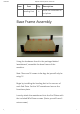
16/01/2019 Shapeoko Assembly Guide - Carbide 3D Item Part Qty Leveling Feet 4 Description install on underside of end plates Base Frame Assembly Using the hardware found in the package labeled ‘wasteboard’, assemble the base frame of the machine. Note: There are 18 screws in the bag, but you will only be using 12. Begin by installing the leveling feet in the corners of each End Plate. Set the 3/4” wasteboard across the front/rear plate.
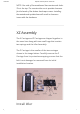
16/01/2019 Shapeoko Assembly Guide - Carbide 3D NOTE: One side of the wasteboard has countersunk holes. This is the top. The countersinks are to provide clearance for the heads of the button head caps screws. Installing the wasteboard upside down will result in clearance issues with the hardware. XZ Assembly The X Carriage and Z Carriage are shipped together in the same box along with two small bags that contain two springs and the Idler Assembly.
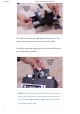
16/01/2019 Shapeoko Assembly Guide - Carbide 3D The Idler Assembly ships already assembled in the proper order. See the image below to verify the ordering of the various components. Carefully remove the nut while ensuring the remaining components stay on the bolt. Insert the bolt through the slot located at the bottom of the plate - shown in the image below. Secure in place by nger-tightening the nut on the opposite side of the X Carriage.
16/01/2019 Shapeoko Assembly Guide - Carbide 3D Align the spindle mount with the bottom set of through holes on the z-carriage. The carbide logo should go right side up, but the position of the pocketed hole on the spindle mount does not matter (left or right is ne). The xed pulley location should be on the left side of the plate, as shown in the photo. For further reference: the eccentric nuts will be on the left side as well.
16/01/2019 Shapeoko Assembly Guide - Carbide 3D them secure and reduce the chance of vibration causing the screws to become loose. Z-Carriage Flip the Z Carriage and orient the Z Carriage so it is as shown in the image below. NOTE: The bearings and belt will now be on the underside. Align the Z-carriage with the bottom of the X-carriage, making sure the eccentrics on the Z-carriage are positioned on the left side, as shown in the image below.
16/01/2019 Shapeoko Assembly Guide - Carbide 3D Examine the four bearings on the Z Carriage and take note of the V-shaped gap between the two black wheels as shown in the image below. Routing the Belt When the Z Carriage is attached to the rails properly, a portion of the belt should be exiting the top and bottom of the Z Carriage as shown in the image below. Slowly pull the bottom portion of the belt and loop it over the Idler as shown. https://docs.carbide3d.
16/01/2019 Shapeoko Assembly Guide - Carbide 3D The Idler can move up and down in its groove. You may have to loosen the nut to move the Idler. Carefully wrap the upper portion of the belt around the top pulley as shown. NOTE: If you had to loosen the Idler nut to move it, move the Idler down to provide some tension on the belt and nger-tighten again so the belt does not come o the Idler. https://docs.carbide3d.
16/01/2019 Shapeoko Assembly Guide - Carbide 3D Tension Screw Carefully place the X/Z Carriage on its back (resting on the motor) as shown in the image below. Slide the Z Carriage all the way to the top until it stops at the two posts shown in the image below. Ensure that you have only nger-tightened the Idler Assembly before tightening the Tensioning Screw. Use the hex wrench to tighten the Tensioning Screw as shown in the image below.
16/01/2019 Shapeoko Assembly Guide - Carbide 3D When the belt is tight, use a 4mm hex key and 10mm wrench to tighten the Idler Assembly as shown in the image below. Install Springs Lay the X/Z Carriage on one of its sides as shown in the image below. Place one of the spring’s loops around the Z Carriage post as shown in the image below. Pull up on the spring and attach the other loop to the X Carriage post as shown in the image below.
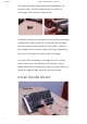
16/01/2019 Shapeoko Assembly Guide - Carbide 3D Using the 2x M5x55mm screws, install into spindle mount. Do not tighten at this point, we will secure these screws after we install the spindle later in this guide. peoko/xxl/xxlassyimage/image_39.jpg) Preparing the Plates https://docs.carbide3d.
16/01/2019 Shapeoko Assembly Guide - Carbide 3D Open the Left and Right Y-Axis carriages and the X/Z carriage. Set carriages on the table as shown. The 3 carriages are shipped to you as complete subassemblies. Thread locker has already been used on all threaded connections. Eccentric Nuts Before proceeding, turn the eccentric nuts so the wheels are at their widest position. Rotate the nut clockwise until the screw is at the most bottom point of the rotation. as shown in the image below.
16/01/2019 Shapeoko Assembly Guide - Carbide 3D Adjust the eccentric nuts for all 3 of the plates (6 eccentrics total). The Z-axis eccentric nuts should not need to be adjusted. Installing the Left Y-Carriage In this step, you will be installing the extrusion with the threaded mounting holes on the back side! The bag labeled ‘extrusions’ contains 24 pieces of M6x12mm button head cap screws. These screws are used to attach the carriages, and the base frame to the extrusions.
/01/2019 Shapeoko Assembly Guide - Carbide 3D Using the carriage boxes as supports at each end of the rail will help hold the rail at the proper height for you to install the screws. You don’t need to tighten these screws all the way. We’ll do that in the ‘squaring the machine’ section. Installing the X/Z Carriage Slide the X/Z Carriage on the rail from the right hand side.
16/01/2019 Shapeoko Assembly Guide - Carbide 3D eccentric nuts should be in the position shown in the following image. You do not need much tension in order for the carriage to be secure. The wheels should only be snug against the rail. After tensioning, the carriage should still slide smoothly across the rail, with only slightly more resistance than without the wheels tightened. The travel should be smooth and ‘bump’ free.
16/01/2019 Shapeoko Assembly Guide - Carbide 3D The gantry is now completely assembled. Installing the Gantry System Slide both the left and right Y-Axis rails through the left and right Y-Axis plates. https://docs.carbide3d.
16/01/2019 Shapeoko Assembly Guide - Carbide 3D Using the box as a support, position the gantry system into the base frame. You may need to loosen the base frame assembly if there is not enough clearance to insert the rails. Slide the gantry system in from the side. If you have two people, you can also set it in from the top. Using a carriage box to support the entire gantry (from the center) Install 2 screws, diagonal from each other, on both sides of the front plate.
16/01/2019 Shapeoko Assembly Guide - Carbide 3D After the front is nished, move around to the back of the machine and install all 4 screws on each side of the gantry. Again, these screws should not be fully tightened. We will do that in the ‘squaring your machine’ section. Moving back to the front of the machine, install the remaining 2 screws on each side of the End Plate.
16/01/2019 Shapeoko Assembly Guide - Carbide 3D The proper routing is: Up from the bottom, Down through the top, Back towards the front. Pull about 2″ of belting back towards the front. Ensure the overlapping teach line up and interlock. After the belt has been run through the clip, ensure the teeth have interlocked with each other and there is roughly 2 inches (50mm) of underlapping belting. Using one of the M5x10mm screws, tighten the belt clip against the plate.
16/01/2019 Shapeoko Assembly Guide - Carbide 3D Working your way towards the other end of the Y-Axis Rail, run the belt between the rail and the anged idlers. Pushing from both sides of the idler, force the belt up and towards the idler. You can also use the 1.5mm hex key to lift the belt between the idlers. Once the belt is accessible, wrap around idler. Using another M5x10mm screw, tension the belt clip against the front of the machine.
16/01/2019 Shapeoko Assembly Guide - Carbide 3D screw can catch a thread into the belt clip nut (as shown). Once the screw is engaged with the nut, tighten the clip with a 4mm allen key. Routing the X Axis Belt Lay the belt across the entire extrusion, threading it below the idlers with the teeth facing down. Using the 1.5mm hex key as a lever, push the timing belt between the idlers. https://docs.carbide3d.
16/01/2019 Shapeoko Assembly Guide - Carbide 3D Using both hands, push the belt in from the outside of the idlers. The belt will bubble up as it travels through the thin gap. Once accessible, grab the loop with your ngers or the allen key and pull enough out so you can grab it with your ngers. Twisting the belt slightly, slide one edge between the pulley and the plate until half of the loop is around the pulley.
16/01/2019 Shapeoko Assembly Guide - Carbide 3D This should be just close enough where the M5x10mm screw can catch a thread into the belt clip nut (as shown above, left image). Once the screw is engaged with the nut, tighten the clip with a 4mm allen key. WARNING: DO NOT OVER-TIGHTEN THE BELT. OVER TIGHTENING THE BELT CAN BEND THE STEPPER MOTOR SHAFT! Home Switches There is 1 home switch per axis of your machine (3 total). Install in the order shown below.
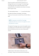
16/01/2019 Shapeoko Assembly Guide - Carbide 3D Install Z-Axis Install the Z-axis switch plate by rst installing 2 25mm x 1mm stando s, using the M5x10mm BHCS included with the kit. PROTIP: It will be easier to install the plate if you do not tighten the stando s at this time. With the stando s installed, place the Z-axis plate in place, and secure with 2 more M5x10mm BHCS as shown in the photo below. https://docs.carbide3d.
16/01/2019 Shapeoko Assembly Guide - Carbide 3D Install X-Axis Install the X-axis plate by using 2 M5x35mm BHCS and 2 M5x25mm spacers, shown below in the photo. Slide the screws through the X-axis plate, attach spacers, then attach entire assembly to the back of the X-axis plate, using the built in nuts. https://docs.carbide3d.
16/01/2019 Shapeoko Assembly Guide - Carbide 3D Install Y-Axis Using 2 M5x35mm BHCS and 2 M5x25mm Spacers, install the Y-axis switch and plate to the outside of the Right Y-axis plate. PROTIP: Before you can use the homing feature, homing will need to be enabled in the software con guration. After assembly is complete, head over to the Enable Homing Article to con gure your software.
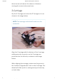
16/01/2019 Shapeoko Assembly Guide - Carbide 3D Wiring If you have not already, remove the shroud from the controller by removing the M6x8mm Socket Head Cap Screws. Inside the shroud you will nd a small selfsealing bag containing 3 rubber grommets and 2 M6x12mm screws. Install the controller on the back of the X-rail. The controller is connected with two M6x12mm screws (button head). https://docs.carbide3d.
16/01/2019 Shapeoko Assembly Guide - Carbide 3D When installing the controller, ensure the orientation matches what is shown in the picture. The USB and Power ports should be facing to the right (as viewed from the same direction as the picture) After the controller has been installed, route the cables from the stepper motors to the controller. The X/Z Assembly works best by using 4 of the zip-ties to create a wire bundle, with a zip tie placed ever 4–6 inches down the bundle. https://docs.carbide3d.
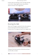
16/01/2019 Shapeoko Assembly Guide - Carbide 3D Route all of the wires through the top of the enclosure. All of the cables can be routed through the center port opening, it’s easiest if you run cables through the grommet one at a time until the entire bundle is together. Leave the grommet out of the port opening until all of the cables have been routed, and travel has been tested. https://docs.carbide3d.
16/01/2019 Shapeoko Assembly Guide - Carbide 3D If you are installing homing switches at this time, route those through the port opening and to their connection points. Notice the orientation of the cables and the order (X/Y/Z from right to left). Attach the X and Z axis stepper motors to their respective ports (labeled on the silkscreen as well). Then, connect the Y1 and Y2 stepper motors to their ports. NOTE: these wires do not cross each other.
16/01/2019 Shapeoko Assembly Guide - Carbide 3D After your wires have been connected to the correct ports, install the enclosure cover using the included M6 x 8mm Socket Head Cap Screws (one on each side). After the enclosure is on, check the travel of your X axis to make sure there is enough slack in the wire bundle to allow full travel. Just slide the X-axis to its farthest extent on both sides and ensure the wires do not pull.
16/01/2019 Shapeoko Assembly Guide - Carbide 3D Squaring Gantry 1. Loosen all of the screws that hold the gantry together (4 on each side), these should still be loose from the initial assembly. 2. Loosen the screws that hold the Y axis rails in place (16 total). These should also still be loose from the initial assembly. 3. Slide the gantry to the front, so both Y plates are touching the front plate. 4.
16/01/2019 Shapeoko Assembly Guide - Carbide 3D 1. Carbide Create User Guide 2. Carbide Motion User Guide 3. Run ‘Hello, World’ 4. Make a set of clamps! 5. See other’s projects for inspiration Need help? support@carbide3d.com Subscribe Share © Carbide 3D 2018, All rights reserved. https://docs.carbide3d.