
Installation guide


9
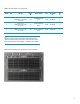
The configuration used to achieve highest performance consists of attaching the VMA directly to the PCIe slots in the
back of the DL980 server using VMA Direct Attach PCIe x8 pass-thru cards. This is the configuration used in the three
solutions described in this paper. VMA can also be configured via Fibre Channel via a 2U HP VMA SAN Gateway that
provides LUN management functions. A maximum of two VMA memory arrays are supported behind one VMA SAN
Gateway for Fibre Channel SAN attach. However, latency will be higher than that achieved with direct attach pass-thru
cards. If an active-active highly available solution is required using Oracle Real Application Clusters (RAC) then you could
use a combination of the HP VMA SAN Gateway with the VMAs to provide a shared storage configuration.
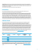
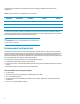
Table 9. DL980 G7 and VMA Storage Performance and Capacity
Attribute
VMA Configuration 1
VMA Configuration 2
VMA Configuration 3
Number of arrays
2
4
8
Potential IOPS
600,000
1,200,000
2,400,000
Bandwidth (GB/s)
2.8
5.6
11.2
Capacity (RAW)
20TB
40TB
80TB
Capacity (Useable)
12TB
24TB
48TB
When the active data of large-scale and high performance applications using Oracle databases is assigned to VMA
appliances, dramatic application acceleration and much higher CPU utilization is achieved. This enables the data center
by supporting high performance random I/O without the need for large DRAM server footprints or thousands of spinning
HDDs.
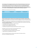
Each VMA3210 is populated with 84 x 128GB solid state memory (SSM) Modules based on Single Layer Cell (SLC) flash
memory devices. VMA Switched Memory technology and VMA’s Flash RAID provide the system with its industry-leading
scalability, data reliability and efficiency:
Hot swappable flash memory modules with 4+1 RAID and 4 spares
System power: less than 120W per Useable Terabyte
Endurance: greater than 8TB Writes per Hour for 5 Years
Redundant power supplies and cooling are provided in all VMA-series Memory Array systems.
Manageability is built into the system with an onboard management controller.
Built-in management processor with command line interface
Front panel status icons and internal status LEDs on each memory board
Appliance with factory-installed VMA controller software.
The optional FC SAN Gateway appliance and vShare software supports a web-based user interface.
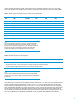
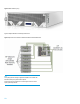
Figure 2 shows a single VMA-series Memory Array.