
Instruction manual

PF2100
Modbus Card Instruction Manual v1.1
©2011 Profire Energy Inc
Jan 5, 2012
Page 15
Testing the Modbus Card
There are a many different ways that you can determine if the Modbus Card is functioning correctly. These should generally be tried in this order:
1. Try to read a register from the PF2100 using the Modbus Master Device on the bus
2. Look at the LEDs on the Modbus Card
3. Use a PC Software Based Modbus Test Program
4. Use a Network Analyzer, Logic Analyzer, or Oscilloscope
Using a Modbus Master
First ensure that the Modbus Master Device that is intended to be used with your final system installation is setup correctly on the same RS-485 bus as the
Modbus Card. Then attempt to read a register from the PF2100 over the Modbus link. Consult “Appendix D – Troubleshooting” to determine which register
address(es) that you want to read and the meaning of the result(s) that you might get back. If the value that comes back is what you expect, then your card and
bus are probably setup correctly.
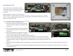
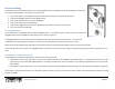
Using the LEDs
If your Modbus Card is powered up, you should see the “RUN” LED blinking at a fixed rate of about 2Hz. In addition, the “RX” LED will blink once briefly every
time that the Modbus Card sees a voltage transition on the bus. The “RX” LED will blink regardless of whether the packet was actually addressed to the Modbus
Card or even had a valid CRC. The “RX” LED is therefore a useful tool to visually see the total amount of traffic (or noise) on the bus. If a successfully received
packet was addressed to the Modbus Card, the “TX” LED will also light up almost at the same time as the “RX” LED indicating that a response has been
transmitted. If some of these LEDs are not behaving as described above, then consult the troubleshooting section of this document for further advice.
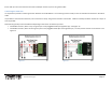
Using a PC Software Based Modbus Test Program
If you cannot figure out what is wrong with your Modbus Card by using the intended Master Device or by looking at the LEDs, you may want to use a laptop with
an RS-485 dongle and some test software to attempt to communicate with the Modbus Card at other locations along your bus. Some examples include:
• The “SeaLINK+485-DB9” available from “Sealevel Systems Inc.” is a USB to RS-485 dongle for Windows PCs.
• “Simply Modbus Master” and “Simply Modbus Slave” are test programs for Windows PCs available from a company called “Simply Modbus” in both paid
and trial versions.
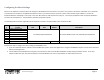
Using a Network Analyzer, Logic Analyzer, or Oscilloscope
A portable Network Analyzer, Logic Analyzer, or Oscilloscope are useful for checking timing, level, and noise issues that might be present on your bus. Be sure to
verify that the Master Device is putting out signals on the bus that are compliant with the specifications for the Modbus Card listed on page 4.