
Instruction manual
PF2100
Modbus Card Instruction Manual v1.1
©2011 Profire Energy Inc
Jan 5, 2012
Page 14
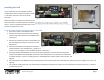
Configuring the Menu Settings
Menu 6 is the expansion card menu where all settings for the Modbus Card can be found. This menu is not present in all versions of firmware so it is important
to verify that your firmware is compatible with expansion cards. From the status menu, press the “menu” button 6 times to get to Menu 6. The text “6 –
Expansion Modules” will display on the screen. Press the “OK” button to view the first menu item, 6.1. You may be prompted to enter the system password if
you have not already done so. The password is Up-Down-Up-Up-Down-Up-OK.
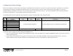
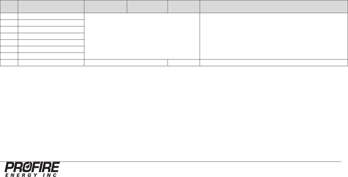
The following table shows the organization of the expansion card menu as implemented in door card FW v1.6.3CE.
Menu
# Prompt Min Max Default Description
6.1
Enable 4
-
20 Exp Card
See 4-20mA Input Card Manual. Not used for Modbus Cards. See 4-20mA Input Card Manual.
6.2
4
-
20 Low Level Setpnt
6.3
4
-
20 High Level Setpnt
6.4
4
-
20 Max Volume
6.5
4
-
20 Volume Units
6.6
4
-
20 Level Span Calibration
6.7
4
-
20 Level Zero Calibration
6.8
Comm Expansion Card
0 (Disabled), 1 to 127 (Enabled)
0 (Disabled)
Used to enable, disable, and set the
address of the Modbus Card.
Follow these steps to configure the menu settings for the Modbus Card:
1. If you are unfamiliar with the operation of the PF2100 menu system, review the “Appendix B – Using the PF2100 Menu System” section of this document
before proceeding further.
2. Set the address of the Modbus Card using menu 6.8. Menu 6.8 is also used to disable the Modbus card by setting the address to zero. A non-zero
address enables the card. Note that every device on the RS-485 bus must have a unique address or data collisions will occur.