PF2100 Modbus Card Instruction Manual v1.
Table of Contents Description ............................................................................................................................................................................................................................................... 1 Quick Start Checklist ..........................................................................................................................................................................................................................
The Pluggable Header ........................................................................................................................................................................................................................ 12 Connecting the Communication Wires .............................................................................................................................................................................................. 12 Connecting the “GND” Pin .................
Analog Tables ..................................................................................................................................................................................................................................... 19 Command Register .............................................................................................................................................................................................................................
Description The Modbus Card is an Expansion Card designed for use with PF2100 Burner Management Systems. It implements a Modbus Slave Device which allows settings and measurements in the PF2100 to be read remotely by a PLC or other remote Master Device. A future firmware update will enable Master Devices to remotely change settings in the PF2100. The protocol used is Modbus RTU and the physical implementation is half-duplex RS-485. The baud rate is user selectable between 9600 and 19200 bps.
Quick Start Checklist Follow these steps in order to install and setup the Modbus Card properly. Check off each step after it is completed to ensure that you don’t miss a step. More detailed information on how to complete each step is located in later sections of this document. Preparation: □ 1. Verify System Requirements. See instructions on page 3. □ 2. Verify Included Hardware. See instructions on page 5. □ 3. Verify DIP Switch Settings. See instructions on page 6. □ 4.
Specifications and System Requirements This manual was written for use with Modbus Cards that have the following model and version: Model Number Hardware Version Firmware Version 1PS167 v1.0 / v2.0 v1.1 / v2.0 PF2100 System Requirements This input card is designed to be used only with PF2100 systems that meet the following requirements: Door Card Terminal Card Hardware Version Firmware Version Hardware Version Firmware Version v1.6 or higher v1.6.3CE or higher v1.61 or higher v1.6.
Modbus Card Specifications The Modbus Card has the following specifications: Spec Operating Temperature: Value -40 C to +60 C RS-485 Signaling: Min Differential Receiver Voltage Absolute Max Receiver Voltage Typical Differential Driver Voltage Maximum Driver Short Circuit Current Termination Receiver Input Impedance 400 mV (A to B) 15 V (A to GND, B to GND) 5 V (Y to Z) +/- 250 mA None or 120 Ohms (user selectable) 96 kOhms Modbus Protocol: Protocol Baud Rate Parity Tx-to-Rx Delay Modbus RTU 9600 or 19
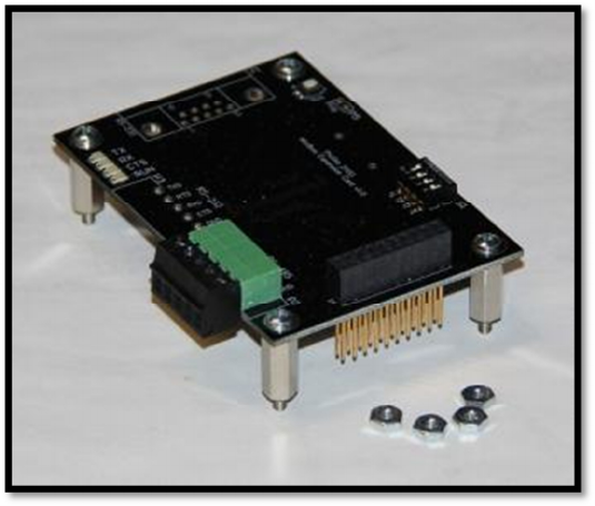
Included Components Your Modbus Card should have come with the following components. If any components are missing, please contact Profire immediately. A picture of these components is included in Figure 2. Item Modbus Card v1.0 / v2.0 Pluggable Header Aluminum Standoffs Phillips Machine Screws Hex Nuts Instruction Manual Quantity 1 1 4 4 4 1 Notes Pre-installed on the card Pre-installed on the card Pre-installed on the card This document Figure 2 PF2100 Modbus Card Instruction Manual v1.
DIP Switch Settings There are 4 DIP switches included on the Modbus Card v1.0 and 8 DIP switches on the Modbus Card v2.0. The default settings for these DIP Switches are shown in Figure 3 and Figure 5 respectively. You should ensure that the DIP switches are set according to your needs. The following tables describe the DIP switch functions: Modbus Card v1.0 # Function 1 Baud Rate 2 3 4 Rx to Tx Delay Unused Termination Modbus Card v2.
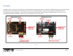
Installing the Card If your system did not have a Modbus Card preinstalled at the factory, follow these steps to install it. Otherwise, skip to the next section of this document. Figure 5 Before you begin, first inspect your terminal card to determine if there is another expansion card (such as a 4-20mA Input Card) already installed in your PF2100 system. There are separate procedures later in this section for the case where there is another card preinstalled and the case where there is not.
Procedure When No Expansion Card is Preinstalled 1. Shut off the power to the PF2100 system. 2. Remove the 4 screws that hold the terminal card in place in the product enclosure. Do not lose these screws as you will need them later. See Figure 9. 3. Carefully install the Modbus Card onto the Terminal Card such that the long pinned header on the Modbus Card mates with the socket P1 on the Terminal Card. Be careful not to bend any pins while doing this.
System Considerations When installing the Modbus Card, it is important to consider the entire system in order to ensure proper operation of all devices. The system consists of all components that are on the same bus including the Master device, all Slave devices, the wiring, repeaters, and bus terminators. The following things should be considered before designing a new RS-485 bus or when adding devices to an existing bus: 1. Cable Type 2. Duplex 3. Wiring Topology 4. Termination 5. Baud Rate 6.
Termination The two devices at the far ends of the bus should both be terminated. All other devices on the bus must NOT be terminated. For Cat-5e cable, a 120 Ohm resistor is used to terminate the devices. The Modbus card has a built-in, jumper selectable 120 Ohm termination resistor. If another cable type is used, an external termination resistor of a different value may be required instead.
Turn-Around Delay RS-485 devices must tri-state when they are done transmitting on the bus in order to allow other devices to communicate. The amount of time required to switch from transmit mode to tri-state or from receive mode to tri-state is called the turn-around delay. Different devices may have different turn-around delays. It is therefore important to ensure that any two devices on the bus that must communicate with each other are setup to accommodate these delays.
Electrical Wiring The following steps should be followed to wire up the pluggable header on the Modbus Card. More detailed instructions for each step can be found later in this section of the document. 1. 2. 3. 4. 5. 6. Disconnect power from the PF2100 to prevent accidentally shorting any component of the system. Remove the pluggable header from the Modbus Card. Wire up the communication pins to the RS-485 Bus. Wire up the “GND” pin to the RS-485 Bus.
Ensure that you use 2 wires from the same color coded pair of wires if you are using Cat-5e cable. Connecting the “GND” Pin It is important to provide a common ground for all devices on the RS-485 bus. The common ground is usually run over an otherwise unused wire in the Cat-5e cable. If your device is not at the end of the bus, use a shunt wire to “drop” the ground connection onto the bus. Make sure to keep the wires used for the “drops” as short as possible.
Configuring the Menu Settings Menu 6 is the expansion card menu where all settings for the Modbus Card can be found. This menu is not present in all versions of firmware so it is important to verify that your firmware is compatible with expansion cards. From the status menu, press the “menu” button 6 times to get to Menu 6. The text “6 – Expansion Modules” will display on the screen. Press the “OK” button to view the first menu item, 6.1.
Testing the Modbus Card There are a many different ways that you can determine if the Modbus Card is functioning correctly. These should generally be tried in this order: 1. Try to read a register from the PF2100 using the Modbus Master Device on the bus 2. Look at the LEDs on the Modbus Card 3. Use a PC Software Based Modbus Test Program 4.
Appendix A – Modbus Background Info Modbus is an industrial control and monitoring protocol originally designed in the 1970s to connect a PLC (“Programmable Logic Controller”) or some other type of Supervisory Computer with one or more RTUs (“Remote Terminal Units”). Modbus is a Master-Slave protocol where the An RTU typically encoding some physical property such as temperature, pressure, pH, or flow rate into a digitally represented number and then sending it in a framed packet on the bus.
Appendix B – Using the PF2100 Menu System Menu Structure The menu system (for door card firmware v1.6.3CE) is comprised of a status menu followed by six numbered menus containing the system settings and other information. When the system is powered on, it will default to displaying the status menu. Each menu has a number of menu items.
Reverting an Edited Menu Item Setting To cancel editing and revert to the previous value, press the “menu” button. The message “Parameter NOT Saved” will display briefly on the screen and the system will advance to the next menu item. Menu Item Setting Storage The settings for the PF2100 System (including those for the Modbus Card) are physically stored on the door card in non-volatile memory. This means that the settings will be retained even if power is lost.
Appendix C – Modbus Register Numbers The following tables list all of the PF2100 Register Numbers that are accessible via the Modbus Card interface. Discrete Table The following registers are all 1-bit in size and are read only in the current firmware version. A future firmware revision may enable some of these to be writable.
Register # 30001/40001 30002/40002 30003/40003 30004/40004 30005/40005 30006/40006 Register Name Run and Valve Status Bits: Bit 1 – RUN Bit 2 – Pilot Bit 3 – Low Fire Bit 4 – High Fire Input Status and Flags: Bit 0 – Level Input Bit 1 – Main solenoid feedback Bit 2 – Pilot solenoid feedback Bit 3 – High Pressure Input Bit 4 – Proof of Closure Bit 5 – ESD Input Bit 6 – Start Input Bit 7 – Low Pressure Bit 8 – Flame Detected Bit 9 – Flame Test Fail Bit 10 – Unit failure Bit 11 – Low or High voltage Bit 12
Appendix D – Troubleshooting If you are having trouble with your Modbus Card, please consult the following resources in this order: 1. Consult the following list of common problems to see if one matches yours. 2. Consult the support section of our website at http://www.profireenergy.com. 3. Contact us on our support line at 1-855-PRO-FIRE (776-3473). Menu 6 Does Not Exist on my PF2100 The firmware version is too old and does not support expansion cards.
The “TX” LED Does Not Light When the Master Sends a Command The address is incorrect, the wiring is incorrect, the baud rate is incorrect, or the card is damaged. • Double check that the Modbus Card has the correct address in the menu 6.8.