
User manual


TVS user manual What you need to know before installing your TVS
13
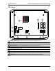
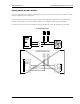
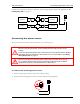
TVS layout
Voltage selection switch: set this switch to the correct voltage before installing your TVS.
Incoming power terminal: connect the incoming power (120/230 VAC, 50/60 Hz) to this terminal.
Temperature probe terminal: connect the temperature probe to this terminal.
Alarm relay terminal: connect an external alarm system or alarm siren to this terminal.
General-purpose relay terminal (STAGE 3): connect single stage (on/off) equipment to this terminal. You can
configure this relay as heat or cool.
Variable stage terminals (VAR 1, VAR 2): connect variable speed fans to these terminals.
Variable stage fuses (F3 for VAR 2, F2 for VAR 1): 12 A, 250 VAC ABC-type ceramic.
Relay fuse (F1): 12 A, 250 VAC ABC-type ceramic.
Display cable: make sure the ribbon cable from the display is properly connected to the socket.
ASSY: ######
S/N: YYYYMMDD-NNN
WO# NNNNN
SH12
115
230
12
L1 NEUT/
L2
45
TEMP
14 15 16
ALARM
30 31
STAGE
3
32 33
VAR 2
STAGE
2
34 35
VAR 1
STAGE
1
1
2
9
7
3 6 4 5
8
1
2
3
4
5
6
7
8
9