MARK-IV UHF NARROWBAND SIGNAL BOOSTER USER’S MANUAL REVISION 0 SUBMITTED BY: CANAM TECHNOLOGY, INC.
CANAM TECHNOLOGY, INC. (CTI) MARK-IV UHF NARROWBAND SIGNAL BOOSTER USER’S MANUAL I. TABLE OF CONTENTS I. II. III. TABLE OF CONTENTS ............................................................................................ 2 TABLE OF FIGURES ................................................................................................. 2 INTRODUCTION ..................................................................................................... 3 Section A. System Description ..................
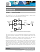
CANAM TECHNOLOGY, INC. (CTI) MARK-IV UHF NARROWBAND SIGNAL BOOSTER USER’S MANUAL III.INTRODUCTION Section A. System Description This system (D.U.T.) is an UHF Narrowband Signal Booster to operate within range 450-512MHz for Land Mobile radio FCC Part 90. AGC MCPA Antenna Rx INPUT AGC . . . RF Tx OUTPUT AGC Figure 1 – UHF Narrowband Signal Booster Basic Block Diagram The system features six or more programmable frequency narrowband filters.
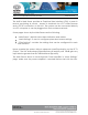
CANAM TECHNOLOGY, INC. (CTI) MARK-IV UHF NARROWBAND SIGNAL BOOSTER USER’S MANUAL The built-in Web Server provides a Graphical User Interface (GUI) to ease in remote monitoring & control. Access is obtained via a PC’s Web Browser and a TCP/IP connection to the Unit. The system can be connected directly to a PC computer or can be plugged into the local area network. Some pages shown by the Web Server are the following: “Main Status”: depicts status alarm indicators and meters.
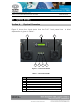
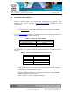
CANAM TECHNOLOGY, INC. (CTI) MARK-IV UHF NARROWBAND SIGNAL BOOSTER USER’S MANUAL IV. QUICK START Section A. Physical Overwiew Figure 2 shows the visual status that the D.U.T. front panel has. explanation is given in Table 1.
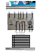
CANAM TECHNOLOGY, INC. (CTI) MARK-IV UHF NARROWBAND SIGNAL BOOSTER USER’S MANUAL Figure 3 shows the connectors and visual status that the D.U.T rear panel has. A brief explanation of each connector is given in Table 2. 1 2 3 8 4 9 5 10 6 11 Figure 3 - Rear Panel details. Table 2 – Rear Panel details.
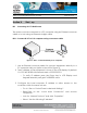
CANAM TECHNOLOGY, INC. (CTI) MARK-IV UHF NARROWBAND SIGNAL BOOSTER Section B. B.1 USER’S MANUAL Start - up Accessing D.U.T. Web Server The system can be connected to a PC computer using an Ethernet crossover cable or to LAN using an Ethernet straight cable. B.1.1 Connect D.U.T to P.C computer using a crossover cable Figure 4 – D.U.T. connected directly to PC computer. 1. Use an Ethernet crossover cable for connect equipment directly to a PC computer LAN port (refer to Item #8 in Figure 3). 2.
CANAM TECHNOLOGY, INC. (CTI) MARK-IV UHF NARROWBAND SIGNAL BOOSTER USER’S MANUAL Configure PC computer IP address as 192.168.100.X (X is a value between 0-255) with Network Mask = 255.255.255.0. Default gateway can be same value as IP address. o Select “Obtain DNS server address automatically”. 4. Open a web browser and access the equipment by typing, in the address bar, the IP address of the equipment (http://192.168.100.80). o Login with username = operator, password = operator. B.1.2 Connect D.
CANAM TECHNOLOGY, INC. (CTI) MARK-IV UHF NARROWBAND SIGNAL BOOSTER B.2 USER’S MANUAL Using and setting up D.U.T 1. Open a web browser and access the equipment by typing, in the address bar, the IP address (http://192.168.100.80) assigned to the equipment. o Login with username = operator, password = operator. o The Main Status page will be displayed if connection available. 2. Go to Filter Settings page to configure the center desired frequencies following filters distribution in Table 3.
CANAM TECHNOLOGY, INC. (CTI) MARK-IV UHF NARROWBAND SIGNAL BOOSTER USER’S MANUAL 3. Go to Main Settings page: o Verify the “Maximum Desired Output Level per Filter” is +27dBm. o Uncheck “Output MCPA Mute” to enable MCPA output. o Press “Apply” button to apply changes.
CANAM TECHNOLOGY, INC. (CTI) MARK-IV UHF NARROWBAND SIGNAL BOOSTER Section C. C.1 USER’S MANUAL RF Connections Connecting the RF Out Port 1. Use a coaxial cable to connect the test instrument to D.U.T. RF Tx Output Port (refer to Item#7 in Figure 3). C.2 Connecting the RF In Port 1. Adjust the RF Generator output power to -60 dBm. 2. Adjust the RF Generator frequency to match the frequencies that have been programmed in Table 4. 3. Use a coaxial cable to connect the RF generator output to D.U.T.
CANAM TECHNOLOGY, INC.